Review
. 2023 Oct 6;13(19):2711.
doi: 10.3390/nano13192711.

Progress of Polymer-Based Dielectric Composites Prepared Using Fused Deposition Modeling 3D Printing

Affiliations
Review

Progress of Polymer-Based Dielectric Composites Prepared Using Fused Deposition Modeling 3D Printing

Xueling Hu et al. Nanomaterials (Basel). .

Abstract

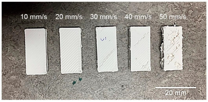
Polymer-based dielectric composites are of great importance in advanced electronic industries and energy storage because of their high dielectric constant, good processability, low weight, and low dielectric loss. FDM (Fused Deposition Modeling) is a greatly accessible additive manufacturing technology, which has a number of applications in the fabrication of RF components, but the unavoidable porosity in FDM 3D-printed materials, which affects the dielectric properties of the materials, and the difficulty of large-scale fabrication of composites by FDM limit its application scope. This study's main focus is on how the matrix, filler, interface, and FDM 3D printing parameters influence the electrical properties of FDM-printed polymer-based dielectric composites. This review article starts with the fundamental theory of dielectrics. It is followed by a summary of the factors influencing dielectric properties in recent research developments, as well as a projection for the future development of FDM-prepared polymer-based dielectric composites. Finally, improving the comprehensive performance of dielectric composites is an important direction for future development.

Keywords: FDM; composite; dielectric; polymer.


Conflict of interest statement

The authors declare no conflict of interest.

Figures

Figure 1
Figure 1
FDM process schematic [13].
Figure 2
Figure 2
Technique flow chart of FDM [14].
Figure 3
Figure 3
(a) Breakdown mechanisms of different dielectric materials; (b) temperature dependence of breakdown field strength [27].
Figure 4
Figure 4
Different types of polarizations and their frequency dependence. Here, Pe, Pi, Pd, and Pint refer to electron polarization, ion polarization, dipole polarization, and interfacial polarization. The dielectric constants and the corresponding losses are indicated by the blue and red lines, respectively. Reproduced with permission from [30]. Copyright American Chemical Society, 2016.
Figure 5
Figure 5
(a) Dielectric constant and (b) dielectric loss versus frequency for PEG-PANI/PVDF composites and (c) dielectric constant and (d) dielectric loss versus frequency for BT/PVDF composites at room temperature. Reproduced with permission from [87]. Copyright Elsevier, 2022.
Figure 6
Figure 6
Dielectric constants and losses of i-G@M-2/PEN composites with different loadings. Reproduced with permission from [96]. Copyright Elsevier, 2023.
Figure 7
Figure 7
Schematic diagram of Ag@C-NC/PVDF nanocomposite preparation and dependence of (a) dielectric constant, (b) dielectric loss, and (c) electrical conductivity on frequency of Ag@C-NC/PVDF nanocomposite [103].
Figure 8
Figure 8
Schematic diagram of the synthesis of Al particles with core@single-shell or core@double-shell structure and the preparation of the corresponding PVDF composites and dielectric properties as a function of frequency for the unfilled polymers and the composites filled with different types of Al fillers. Filler types: (a) nc-Al2O3 single-shell-coated Al particles (b) nc-Al2O3 and c-Al2O3 double-shell-coated Al particles in order from the inside to the outside, (c) c-Al2O3 and nc-Al2O3 double-shell-coated Al particles in order from the inside to the outside, (d) c-Al2O3 single-shell-coated Al particles. Reproduced with permission from [104]. Copyright Elsevier, 2019.
Figure 9
Figure 9
Paraelectric–ferroelectric (P-F) structure route and composite film preparation process. (a) P-F structure design with enhanced dielectricity and energy storage. (b) Monolayer composite preparation process and multicore model for PDA@KNb3O8 rod/polymer interface. Reproduced with permission from [109]. Copyright American Chemical Society, 2022.
Figure 10
Figure 10
Electric and dielectric properties of the PDA@KNb3O8/PMMA-P(VDF-HFP) composite films. (a) Frequency-dependent dielectric constant and (b) dielectric loss. (c) Weibull distributions. (d) Shape parameters (β) histogram and derived breakdown strengths (BDS). Reproduced with permission from [109]. Copyright American Chemical Society, 2022.
Figure 11
Figure 11
Energy storage properties of PDA@ PDA@KNb3O8/PMMA-P(VDF-HFP) composite films. (a) Ferroelectric unipolar P−E loops. (b) Current variation of different filler contents with the applied voltages. (c) Maximum polarization (Pmax), residual polarization (Pr), and net polarization (Pmax − Pr) as a function of the PDA@KNb3O8-based fillers. (d) Comparison of discharge energy storage density (Ud) and energy storage efficiency (η) among this work and some latest reports. (e) Discharge efficiency and energy density of the composite films. Reproduced with permission from [109]. Copyright American Chemical Society, 2022.
Figure 12
Figure 12
FDM 3D-printed test samples using printing speeds of 10–50 mm/s [118].
Figure 13
Figure 13
Layer height vs. relative permittivity (εr) and loss tangent (tanδ) [118].
Figure 14
Figure 14
(a) Material infill (%) vs. relative permittivity (εr) and loss tangent (tanδ); (b) examples of built test samples with variable material infill [118].
Figure 15
Figure 15
Stages in the fabrication of conductive inclusions and RF devices. (left) Filling of the bodies either via hot water bath injection molding of the conductors, (center) production of dielectric bodies with buried canals to contain the conductors, or (right) directly injecting molten Field’s alloy via a heated syringe into the as-printed body warmed in situ on the printer hotbed. The arrows point to separate methods of molding different bodies [125].

References

    1. Tian Y., Zeng G., Rutt A., Shi T., Kim H., Wang J., Koettgen J., Sun Y., Ouyang B., Chen T., et al. Promises and Challenges of Next-Generation “Beyond Li-ion” Batteries for Electric Vehicles and Grid Decarbonization. Chem. Rev. 2021;121:1623–1669. doi: 10.1021/acs.chemrev.0c00767. - DOI - PubMed
    1. Kumar S., Saeed G., Zhu L., Hui K.N., Kim N.H., Lee J.H. 0D to 3D carbon-based networks combined with pseudocapacitive electrode material for high energy density supercapacitor: A review. Chem. Eng. J. 2021;403:126352. doi: 10.1016/j.cej.2020.126352. - DOI
    1. Xie Z., Liu D., Xiao Y., Wang K., Zhang Q., Wu K., Fu Q. The effect of filler permittivity on the dielectric properties of polymer-based composites. Compos. Sci. Technol. 2022;222:109342. doi: 10.1016/j.compscitech.2022.109342. - DOI
    1. Wu X., Chen X., Zhang Q.M., Tan D.Q. Advanced dielectric polymers for energy storage. Energy Storage Mater. 2022;44:29–47. doi: 10.1016/j.ensm.2021.10.010. - DOI
    1. Palani Velayuda Shanmugasundram H.P., Jayamani E., Soon K.H. A comprehensive review on dielectric composites: Classification of dielectric composites. Renew. Sustain. Energy Rev. 2022;157:112075. doi: 10.1016/j.rser.2022.112075. - DOI

LinkOut - more resources