. 2023 Nov;26(11):1994-2004.
doi: 10.1038/s41593-023-01456-8. Epub 2023 Oct 19.

Non-invasive temporal interference electrical stimulation of the human hippocampus

Affiliations

Non-invasive temporal interference electrical stimulation of the human hippocampus

Ines R Violante et al. Nat Neurosci. 2023 Nov.

Erratum in

Abstract

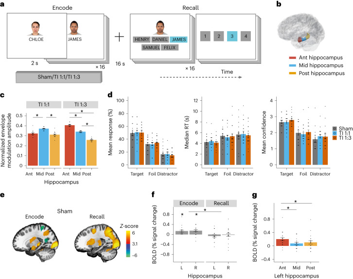
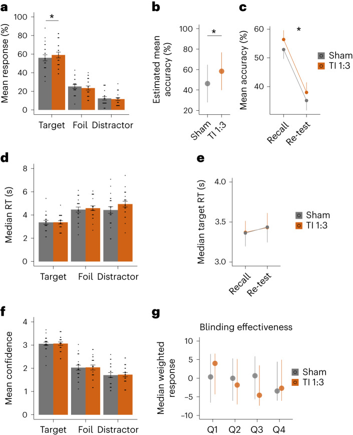
Deep brain stimulation (DBS) via implanted electrodes is used worldwide to treat patients with severe neurological and psychiatric disorders. However, its invasiveness precludes widespread clinical use and deployment in research. Temporal interference (TI) is a strategy for non-invasive steerable DBS using multiple kHz-range electric fields with a difference frequency within the range of neural activity. Here we report the validation of the non-invasive DBS concept in humans. We used electric field modeling and measurements in a human cadaver to verify that the locus of the transcranial TI stimulation can be steerably focused in the hippocampus with minimal exposure to the overlying cortex. We then used functional magnetic resonance imaging and behavioral experiments to show that TI stimulation can focally modulate hippocampal activity and enhance the accuracy of episodic memories in healthy humans. Our results demonstrate targeted, non-invasive electrical stimulation of deep structures in the human brain.


Conflict of interest statement

N.G. and E.S.B. are inventors of a patent on the technology, assigned to MIT. E.S.B., N.G., N.K., A.P.-L. and E.N. are co-founders of TI Solutions AG, a company committed to producing hardware and software solutions to support TI research. A.P.-L. is inventor on several issued and pending patents on the real-time integration of non-invasive brain stimulation with electroencephalography and MRI, and applications of non-invasive brain stimulation in various neurological disorders, as well as digital biomarkers of cognition and digital assessments for early diagnosis of dementia. The remaining authors declare no competing interests.

Figures

Fig. 1
Fig. 1. Fundamentals of TI hippocampal stimulation and validation using computational modeling and cadaver measurements.
Concept of TI hippocampal stimulation: a, Two current sources I1 and I2 are applied simultaneously via electrically isolated pairs of scalp electrodes (orange and green) at kHz frequencies f1 and f2, with a small frequency difference Δf = f1 − f2 within the range of neural activity. The currents generate oscillating electric fields E1(t) and E2(t) inside the brain (orange and green arrows, respectively). Superposition of these fields, E1(t) + E2(t), results in an envelope amplitude that is modulated periodically at Δf. The peak amplitude of the envelope modulation can be localized in deep brain structures such as the hippocampus (highlighted in red). b, Schematic of electrode configuration targeting the left hippocampus. Electrodes e1 and e2 formed one electrode pair (orange) and electrodes e3 and e4 another (green), corresponding to I1 and I2 in a. e1 and e3 were located at nasion plane of the left hemisphere, symmetrically above the anterior–posterior midline of the hippocampus (5 cm distance between electrode centers). e2 and e4 were located at a plane above the eyebrow on the right hemisphere (approximately 16 cm distance between electrode centers). Electrodes were 1.5 cm × 1.5 cm square with rounded corners for ex vivo and in vivo experiments and circular 2 cm diameter for computational modeling. c, Illustration of steering of the TI stimulation locus along the hippocampal longitudinal axis. TI stimulation with 1:1 current ratio (‘TI 1:1’) and stimulation locus in the middle region (left); TI stimulation with 1:3 current ratio (‘TI 1:3’) and locus in the anterior region (right). By reducing the current amplitude in one electrode pair and increasing it in the second while keeping the current sum fixed, the stimulation locus can be steered toward the electrode pair with the smaller current amplitude. Computation of TI stimulation locus in a human anatomical model: d, Schematic of the ROIs in the left (stimulated) hippocampus and its overlying cortex; Ant, anterior; Mid, middle; Post, posterior. e, Left: fields’ envelope modulation amplitude. Right: fields’ absolute amplitude; for the ROIs shown in d. Values are median ± s.d. normalized to the hippocampal value here and thereafter (n indicates number of voxels (nvox) per ROI: Cortex (Crtx), Crtx Ant 48,103, Crtx Mid 43,247, Crtx Post 42,656, Hippocampus 50,349). For whole-brain electric field modeling, see Supplementary Fig. 1a. Note that the cortex ROIs are more heterogeneous than the hippocampus as these include gray matter with different folding and white matter tissue. f, Envelope modulation amplitude in hippocampal ROIs (for ROI schematic, see Fig. 2b) during TI 1:1 and TI 1:3 stimulations (n indicates nvox: Ant 22,651, Mid 17,718, Post 9,980); for additional current ratios, see Supplementary Fig. 1. Measurement of TI stimulation locus in a human cadaver (I1 = 2 kHz, 1 mA; I2 = 2.005 kHz, 1 mA): g, Left: CT head image with intracranial electrode leads a, b and c implanted in the left mesial temporal lobe. Each electrode consisted of 15 electrode contacts; black contour, approximate location of the left hippocampus; orange and green stimulation electrodes. Middle: amplitudes of the envelope modulation in the left (stimulated) hippocampus and its overlying cortex showing higher envelope amplitude at the hippocampus (LMM, two-sided paired t-test, t(2) = −5.515, P = 0.0345, n = 3 electrodes). Right: absolute amplitudes in the left hippocampus and overlying cortex, showing higher absolute amplitude in the overlying cortex (LMM, two-sided paired t-test, t(2) = 7.051, P = 0.0195). Dots represent individual electrodes. See Supplementary Table 1 for full statistics and Supplementary Fig. 2 for additional amplitude maps. h, Envelope modulation ratio versus depth for electrode b, showing increasing envelope modulation with depth. i, Anterior (Ant) to posterior (Post) envelope modulation amplitude for the TI 1:1 and TI 1:3 conditions, showing higher Ant/Post amplitudes for the TI 1:3 condition (two-sided paired t-test, t(7) = −7.765, P = 1.204 × 10−4, n = 8 hippocampal electrode contacts); envelope modulation amplitudes in the anterior electrode a were normalized to the posterior electrode c. Dots represent individual contacts in the hippocampal region and are color coded by depth (cold colors for more superficial contacts and warmer colors for deeper contacts). Asterisks identify significant differences, P < 0.05. Bar plots show median ± s.d.
Fig. 2
Fig. 2. Experimental design, BOLD signal during sham and hippocampal fields.
a, The face–name task was composed of nine blocks of encoding and recall. Each block contained 16 unique face–name pairs followed by a delay and a recall period, where participants tried to select the correct name for each face out of five options (that is, one target, two foil names that were present in the block but associated with a different face, and two distractor names that were not present during the task). After each name selection, participants were asked to rate their choice confidence (1 (not confident at all) to 4 (extremely confident)). b, Schematic of the Ant, Mid and Post ROIs along the hippocampal longitudinal axis. c, Participants’ envelope modulation amplitude in hippocampal ROIs during TI 1:1 and TI 1:3 stimulations, computed with individualized MRI-based anatomical models; n = 16 participants (Supplementary Fig. 3). Showing a steering of the envelope amplitude peak from Mid hippocampal ROI during TI 1:1 stimulation (LMM, F(2,30) = 26.05, P = 2.7 × 10−7; post hoc comparisons using the Tukey honestly significant difference (HSD) test, two-sided, Mid–Post/Ant, P < 0.0001, Post–Ant, P = 0.420) to Ant hippocampal ROI during TI 1:3 stimulation (LMM, F(2,30) = 359.62, P < 2.2 × 10−16; post hoc comparisons using the Tukey HSD test, two-sided, P < 0.0001 between all ROIs); amplitudes were normalized to total hippocampal exposure. For full statistics, see Supplementary Table 2. d, Participant’s performance across stimulation conditions, sham (gray), TI 1:1 (blue) and TI 1:3 (orange). Left: percentage mean response selection for each response category, showing a higher proportion of target selection compared to foils or distractors (probability of correct selection by chance was 0.2). Middle: median reaction time (RT) during recall, showing faster reaction times for target selection. Right: mean confidence rating for each response category, showing higher confidence ratings for correct associations compared to foils and distractors. There was no effect of stimulation for response type or reaction time. There was an effect of TI 1:3 stimulation for confidence rating. There was no interaction between stimulation and response category for any of the behavioral metrics. For full statistics, see Supplementary Table 4. e, Whole-brain group z-score change in BOLD signal during encode and recall. f, Group median change in BOLD signal in the left (L) and right (R) hippocampi in sham condition blocks. Showing significant BOLD signal increase during the encode (one-sample t-test, two-sided, left hippocampus t(19) = 3.70, P = 0.003; right hippocampus t(19) = 3.92, P = 0.003; FDR corrected), but not recall (left hippocampus t(19) = −1.28, P = 0.287; right hippocampus t(19) = −0.25, P = 0.805; FDR corrected); and significant effect of task stage (LMM, F(1,57) = 20.492, P = 3.09 × 10−5; for full statistics, see Supplementary Table 5. g, Group median change in BOLD signal in the anterior (Ant), middle (Mid) and posterior (Post) regions of the left hippocampus during the encoding stage in the sham condition. Showing a larger BOLD signal increase in the Ant hippocampal region in relation to the Mid and Post regions (LMM, F(2,38) = 8.72, P = 7.658 × 10−4; post hoc comparisons using the Tukey HSD test, Ant–Mid, P = 0.0008; Ant–Post, P = 0.0137; Mid–Post, P = 0.5518); for full statistics, see Supplementary Table 6. Asterisks identify significant differences, P < 0.05. Bar plots show mean and SE, black dots show individual participant data. Images in e were thresholded at Z > 3.1, with a cluster significance level of P < 0.05, and are displayed in x = −21 plane of the MNI template. n = 20 throughout except for c where n = 16.
Fig. 3
Fig. 3. Effect of TI stimulation on hippocampal episodic memory activity.
a, Whole-brain group z-score change in BOLD signal during encode and recall stages of the task for TI 1:1 and TI 1:3 stimulation conditions. Note the increase in BOLD signal in the left hippocampus during encode for the TI 1:1 condition, similar to the pattern observed for sham (Fig. 2e), but not for the TI 1:3 condition. b, Comparison of group median change in BOLD signal between stimulation conditions, in the left (stimulated) hippocampus during encoding and recall stages. Showing an effect of stimulation and reduction in the evoked BOLD signal in the left hippocampus during encoding stage by TI 1:3 stimulation (LMM, effect of stimulation F(2,95) = 3.2, P = 0.0443; task stage F(1,95) = 44.84, P = 1.49 × 10−9; interaction F(2,95) = 2.96, P = 0.056; post hoc comparisons using the Tukey honestly significant difference test, two-sided, Encode: Sham–TI 1:1, P = 0.953; Sham–TI 1:3, P = 0.006; TI 1:1–TI 1:3, P = 0.015); for full statistics, see Supplementary Table 8. c, Comparison of group median change in BOLD signal between stimulation conditions, in the Ant, Mid and Post regions of the left hippocampus during the encoding stage; for ROIs schematic, see Fig. 2b. There is a significant main effect of stimulation in the evoked BOLD signal during the TI 1:3 stimulation; for full statistics, see Supplementary Table 9. d, Voxelwise group-level contrasts comparing stimulation conditions in the left hippocampus, confirming higher BOLD signal for the sham and TI 1:1 conditions compared to TI 1:3. No significant voxels for the comparison between sham and TI 1:1, confirming the results observed in the hippocampal ROIs. e, Group median change in BOLD signal in the left hippocampus for memory associations encoded correctly (green) and incorrectly (gray). Showing significantly higher BOLD signal for correct compared to incorrect associations in the left hippocampus during sham (LMM, effect of response type (correct, incorrect) F(1,95) = 11.09, P = 0.001), and TI 1:3, (LMM, effect of response type, F(1,95) = 6.6, P = 0.0117); for full statistics, see Supplementary Fig. 4 and Supplementary Table 10. f, Voxelwise group-level contrasts comparing correctly and incorrectly encoded associations in the left hippocampus, showing that BOLD signal during the formation of correct associations is predominantly modulated in a cluster located in the anterior portion of the hippocampus for sham and TI 1:3 conditions, while no significant voxels were observed for the TI 1:1 condition. g, Same as b but for the right hippocampus, where there is no effect of stimulation; for full statistics, see Supplementary Table 8. h, Comparison of group median percentage change in BOLD signal between stimulation conditions, in the anterior (Ant), Middle (Mid) and posterior (Post) regions of the overlying cortex; for ROIs schematic, see Fig. 1d; for full statistics, see Supplementary Table 12. No difference in the BOLD signal change between stimulation conditions. Similar results were obtained for the brain regions underneath the stimulation electrodes in the right hemisphere; for full statistics, see Supplementary Fig. 5 and Supplementary Table 13. Asterisks identify significant differences, P < 0.05. Bar plots show mean and SE, and black dots show individual participant data. Images in a were thresholded at Z > 3.1, with a cluster significance level of P < 0.05, and are displayed in x = −21 plane of the MNI template. Images in d and f were thresholded at significance level of P < 0.05, TFCE FWE corrected, voxelwise permutation-based t-tests on the ROI. n = 20 throughout except for h where n = 16.
Fig. 4
Fig. 4. TI stimulation change in hippocampal–cortical FC.
a, AT (purple) and PM (green) hippocampal–cortical networks. b, Group mean change (% signal change) in FC between the anterior (Ant), Middle (Mid) and posterior (Post) regions of the left (L) hippocampus and the AT and PT networks during encode and recall task stages in sham blocks (that is, without stimulation) for the contrast correct > incorrect. Showing a larger connectivity between the Ant and Mid regions of the L hippocampus and the AT network during encoding of successful associations; (one-sample t-tests, two-sided; Ant → AT, P = 0.0223, P(FDR) = 0.1336; Mid → AT, P = 0.0024, P(FDR) = 0.0287); **P < 0.05 FDR corrected; *P < 0.05 uncorrected; for full statistics, see Supplementary Table 14. c, Effect of TI stimulation on FC, showing the same as b but comparing changes between stimulation conditions during encoding stage in which a connectivity increase was observed in sham blocks. A reduction in FC by both TI 1:1 and TI 1:3 stimulations (relative to sham) and, when comparing the TI stimulations, a larger connectivity in the Mid region during TI 1:1 and in the Ant region during TI 1:3 (LMM with significant three-way interaction between stimulation type, seed and network, F(4,1576) = 2.54, P = 0.038; post hoc comparisons using the Tukey honestly significant difference test, two-sided; Ant → AT: TI 1:1–Sham, P = 0.0010, TI 1:3–TI 1:1, P = 0.0082; Mid → AT: TI 1:1–Sham, P = 0.0059, TI 1:3–Sham, P < 0.0001, TI 1:3–TI 1:1, P = 0.0232); *P < 0.05; for full statistics, see Supplementary Table 14). n = 20 throughout. ‘→’ indicates the direction of the connectivity from seed to target.
Fig. 5
Fig. 5. Probing the effect of hippocampal TI stimulation on behavioral function.
a, Comparison of participants’ memory performances during recall between sham (gray) and TI 1:3 (orange) across response type (target, foil and distractor), showing higher probability of target responses, that is, face–name pairs correctly remembered during TI (GLMM, χ2(2) = 6.353, P = 0.0417; post hoc paired t-tests, two-sided, Sham–TI 1:3; Target, P = 0.0068; Foils, P = 0.1418, P = 0.3836). b, Estimated mean accuracy for sham and TI 1:3, as estimated using a mixed-effects logistic regression model for correct and incorrect responses and independent random-effect terms for ‘participant’, ‘session’ and ‘task block’, showing higher odds of correct recall during TI stimulation (logit scale; GLMM, χ2(2) = 5.857, P = 0.0155). c, Comparison of mean accuracy for target selections between recall and re-test (30 min after first recall, for items correctly remembered at recall) for sham and TI 1:3, showing that target selection was higher for TI 1:3 condition at both time points (GLMM, main effect of stimulation, χ2(1) = 7.581, P = 0.006). d, Same as a but for median reaction time (RT), showing no differences between stimulation conditions. e, Same as b but for median RT for target responses, showing no significant difference between recall and re-test or stimulation conditions. f, Same as c but for mean confidence ratings, which were similar between stimulation conditions. g, Blinding effectiveness. Shown are median weighted scores and 95% confidence intervals for TI 1:3 and sham conditions. Participants were asked at four time points during each session (indicated by a Q on the x axis) whether they thought they had stimulation and how confident they were (1 is not confident at all; 10 is extremely confident). The two questions were combined into a weighted score, whereby a ‘yes’ answer was assigned a +1 value and ‘no’ answer a value of −1, which were then multiplied by the confidence rating. Thus, a positive score on the y axis indicates that participants reported having stimulation, and negative score not having stimulation. No significant effects of stimulation; for full statistics, see Supplementary Table 24. In af, bar or dot plots show mean and SE, and black dots show individual participant data. Asterisks indicate significant differences between stimulation conditions. For full statistics, see Supplementary Table 16. n = 21 throughout.

References

    1. Silberberg D, Anand NP, Michels K, Kalaria RN. Brain and other nervous system disorders across the lifespan—global challenges and opportunities. Nature. 2015;527:S151–S154. doi: 10.1038/nature16028. - DOI - PubMed
    1. O’Brien PL, Thomas CP, Hodgkin D, Levit KR, Mark TL. The diminished pipeline for medications to treat mental health and substance use disorders. Psychiatr. Serv. 2014;65:1433–1438. doi: 10.1176/appi.ps.201400044. - DOI - PMC - PubMed
    1. Gravitz L. Drugs: a tangled web of targets. Nature. 2011;475:S9–S11. doi: 10.1038/475S9a. - DOI - PubMed
    1. Benabid AL, Chabardes S, Mitrofanis J, Pollak P. Deep brain stimulation of the subthalamic nucleus for the treatment of Parkinson’s disease. Lancet Neurol. 2009;8:67–81. doi: 10.1016/S1474-4422(08)70291-6. - DOI - PubMed
    1. Greenberg BD, et al. Deep brain stimulation of the ventral internal capsule/ventral striatum for obsessive–compulsive disorder: worldwide experience. Mol. Psychiatry. 2010;15:64–79. doi: 10.1038/mp.2008.55. - DOI - PMC - PubMed

LinkOut - more resources