

Asymptotic dispersion engineering for ultra-broadband meta-optics
- PMID: 37863896
- PMCID: PMC10589226
- DOI: 10.1038/s41467-023-42268-5
Asymptotic dispersion engineering for ultra-broadband meta-optics
Erratum in
-
Author Correction: Asymptotic dispersion engineering for ultra-broadband meta-optics.Nat Commun. 2023 Nov 21;14(1):7591. doi: 10.1038/s41467-023-43525-3. Nat Commun. 2023. PMID: 37989997 Free PMC article. No abstract available.
Abstract
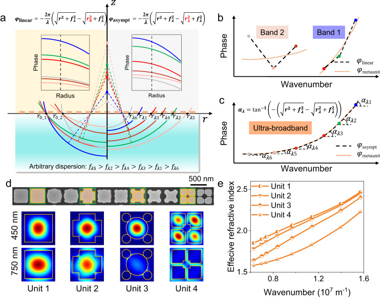
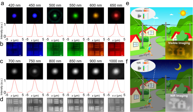
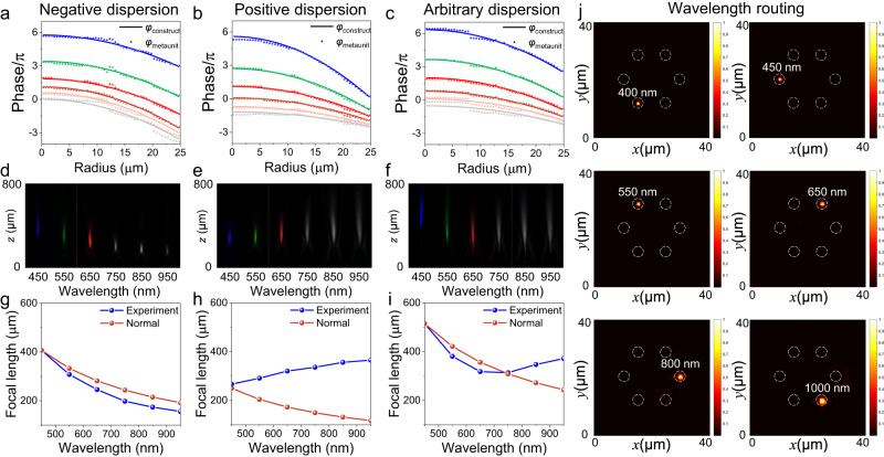
Dispersion decomposes compound light into its monochromatic components, which is detrimental to broadband imaging but advantageous for spectroscopic applications. Metasurfaces provide a unique path to modulate the dispersion by adjusting structural parameters on a two-dimensional plane. However, conventional linear phase compensation does not adequately match the meta-unit's dispersion characteristics with required complex dispersion, hindering at-will dispersion engineering over a very wide bandwidth particularly. Here, we propose an asymptotic phase compensation strategy for ultra-broadband dispersion-controlled metalenses. Metasurfaces with extraordinarily high aspect ratio nanostructures have been fabricated for arbitrary dispersion control in ultra-broad bandwidth, and we experimentally demonstrate the single-layer achromatic metalenses in the visible to infrared spectrum (400 nm~1000 nm, NA = 0.164). Our proposed scheme provides a comprehensive theoretical framework for single-layer meta-optics, allowing for arbitrary dispersion manipulation without bandwidth restrictions. This development is expected to have significant applications in ultra-broadband imaging and chromatography detection, among others.
© 2023. Springer Nature Limited.
Conflict of interest statement
The authors declare no competing interests.
Figures

Similar articles
-
Broadband achromatic dielectric metalenses.Light Sci Appl. 2018 Nov 7;7:85. doi: 10.1038/s41377-018-0078-x. eCollection 2018. Light Sci Appl. 2018. PMID: 30416721 Free PMC article.
-
Mitigating Chromatic Dispersion with Hybrid Optical Metasurfaces.Adv Mater. 2019 Jan;31(3):e1805555. doi: 10.1002/adma.201805555. Epub 2018 Nov 23. Adv Mater. 2019. PMID: 30468543
-
All-silicon polarization-independent broadband achromatic metalens designed for the mid-wave and long-wave infrared.Opt Express. 2023 Dec 18;31(26):44340-44352. doi: 10.1364/OE.506471. Opt Express. 2023. PMID: 38178507
-
Optical metalenses: fundamentals, dispersion manipulation, and applications.Front Optoelectron. 2022 May 18;15(1):24. doi: 10.1007/s12200-022-00017-4. Front Optoelectron. 2022. PMID: 36637532 Free PMC article. Review.
-
Chromatic Dispersion Manipulation Based on Metalenses.Adv Mater. 2020 Jul;32(27):e1904935. doi: 10.1002/adma.201904935. Epub 2019 Dec 11. Adv Mater. 2020. PMID: 31823480 Review.
Cited by
-
Metasurface higher-order poincaré sphere polarization detection clock.Light Sci Appl. 2025 Jan 26;14(1):63. doi: 10.1038/s41377-024-01738-1. Light Sci Appl. 2025. PMID: 39863612 Free PMC article.
-
On-chip integration of achromatic metalens arrays.Nat Commun. 2025 Aug 12;16(1):7485. doi: 10.1038/s41467-025-62539-7. Nat Commun. 2025. PMID: 40796744 Free PMC article.
-
Synthesized dispersion-engineered elastic metasurfaces for achromatic focusing and harvesting across the audible to ultrasound ranges.Proc Natl Acad Sci U S A. 2025 May 6;122(18):e2425407122. doi: 10.1073/pnas.2425407122. Epub 2025 May 1. Proc Natl Acad Sci U S A. 2025. PMID: 40310454
-
3D ultra-broadband optically dispersive microregions in lithium niobate.Nat Commun. 2025 Jul 2;16(1):6086. doi: 10.1038/s41467-025-61317-9. Nat Commun. 2025. PMID: 40603835 Free PMC article.
-
Evolution of dispersion-engineered metasurfaces: Debye relaxation and folded path concept.Light Sci Appl. 2025 Jun 24;14(1):223. doi: 10.1038/s41377-025-01890-2. Light Sci Appl. 2025. PMID: 40555712 Free PMC article.
References
-
- Powell I. Lenses for correcting chromatic aberration of the eye. Appl. Opt. 1981;20:4152. - PubMed
-
- Yang Z, Albrow-Owen T, Cai W, Hasan T. Miniaturization of optical spectrometers. Science. 2021;371:eabe0722. - PubMed
-
- Ishio H, Minowa J, Nosu K. Review and status of wavelength-division-multiplexing technology and its application. J. Lightwave Technol. 1984;2:448–463.
-
- Huang YW, et al. Aluminum plasmonic multicolor meta-hologram. Nano Lett. 2015;15:3122–3127. - PubMed
Grants and funding
LinkOut - more resources
Full Text Sources
