Review
. 2023 Oct 12:32:222-241.
doi: 10.1016/j.bioactmat.2023.09.022. eCollection 2024 Feb.

Design and fabrication of customizable microneedles enabled by 3D printing for biomedical applications

Affiliations
Review

Design and fabrication of customizable microneedles enabled by 3D printing for biomedical applications

Jia Min Loh et al. Bioact Mater. .

Abstract

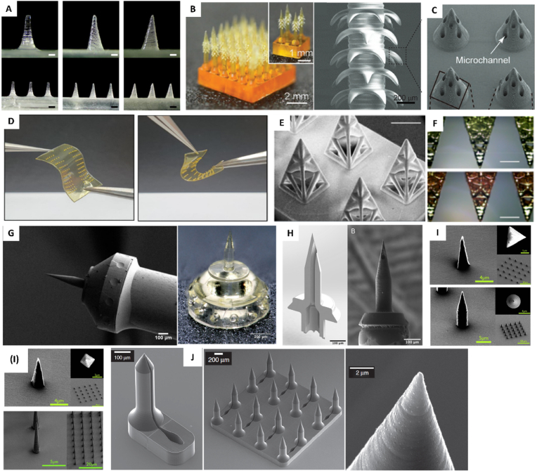
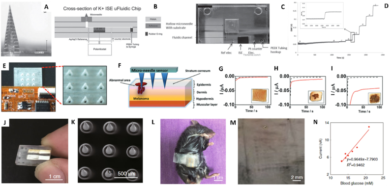
Microneedles (MNs) is an emerging technology that employs needles ranging from 10 to 1000 μm in height, as a minimally invasive technique for various procedures such as therapeutics, disease monitoring and diagnostics. The commonly used method of fabrication, micromolding, has the advantage of scalability, however, micromolding is unable to achieve rapid customizability in dimensions, geometries and architectures, which are the pivotal factors determining the functionality and efficacy of the MNs. 3D printing offers a promising alternative by enabling MN fabrication with high dimensional accuracy required for precise applications, leading to improved performance. Furthermore, enabled by its customizability and one-step process, there is propitious potential for growth for 3D-printed MNs especially in the field of personalized and on-demand medical devices. This review provides an overview of considerations for the key parameters in designing MNs, an introduction on the various 3D-printing techniques for fabricating this new generation of MNs, as well as highlighting the advancements in biomedical applications facilitated by 3D-printed MNs. Lastly, we offer some insights into the future prospects of 3D-printed MNs, specifically its progress towards translation and entry into market.

Keywords: 3D printing; Biosensing; Drug delivery; Extraction of biological specimen; Microneedles.


Conflict of interest statement

The authors declare no conflicts of interest.

Figures

Image 1
Graphical abstract
Fig. 1
Fig. 1
Schematic diagram showing 3D-printed MNs from conceptualization using computer-aided design designs to fabrication by material deposition and vat polymerization, and subsequently uses in biomedical applications including transdermal drug delivery, extraction of biological specimen and biosensing.
Fig. 2
Fig. 2
3D printing techniques for MNs: (A) Stereolithography (SLA); (B) Digital light processing (DLP); (C) Continuous liquid interface production (CLIP); (D) Two-photon polymerization (TPP); (E) Fused deposition modelling (FDM); (F) Material jetting (MJ).
Fig. 3
Fig. 3
MNs fabricated with various material deposition 3D-printing techniques. Material Extrusion: (A) SEM images showing effect of chemical etching on reducing FDM-printed MN tip size (Adapted with permission from Ref. [8]). (B) Microscopic images of FDM-printed PLA MNs showing reduced width and thickness of MNs by chemical etching (Adapted with permission from Ref. [76]). (C) SEM images showing straight FDM-printed PLA MNs obtained after chemical etching (Adapted with permission from Ref. [84]). Material Jetting: SEM images of SLA-printed (D) spear-shaped MNs (Adapted with permission from Ref. [92]) and (E) pyramid MNs (Adapted with permission from Ref. [93]), coated with insulin coating formulations using MJ technique. (F) Microscopic images of MNs with (left) 25 drops and (right) 100 drops of formulation loaded at the tip using piezoelectric dispensing MJ technique (Reproduced with permission from Ref. [91]). (G) MNs printed on a flexible base of a different material using MJ technique; Microscopic view of MJ-printed MNs loaded with red dye (Adapted with permission from Ref. [95]). (H) Hydrogel MNs with different lengths and dyes, printed using material jetting; Image displaying flexibility of the MJ-printed MNs and patch backing in conforming to the bent porcine skin; Fluorescence images showing capability of filling MJ-printed MNs with hydrogels post-printing; Fluorescence image of porcine skin showing deposition of fluorescence by MJ-printed MN array with MNs of different lengths loaded with hydrogels containing different fluorescent markers (Adapted with permission from Ref. [96]).
Fig. 4
Fig. 4
MNs fabricated with various VP 3D-printing techniques. (A) Stereomicroscope images of SLA-printed MNs, showing improved MN tip diameter with increasing printing angles ranging from 0° to 60° to XY-axes (Reproduced with permission from Ref. [100]). (B) Bio-inspired MNs with backward-facing barbs; SEM image of backward-facing barbs (Adapted with permission from Ref. [82]). (C) SEM image of DLP-printed MNs with 8 microchannels with diameter of 40 μm (Adapted with permission from Ref. [105]). (D) DLP-printed silk fibroin MNs with riboflavin photoinitiator on a flexible backing (Adapted with permission from Ref. [34]). (E) SEM image of CLIP-printed lattice MN patches; (F) Optical images of CLIP-printed lattice MNs after taking up liquid containing food colouring (Adapted with permission from Ref. [109]). (G) SEM image showing TPP-printed MN for perforation of RWM attached onto a 25G syringe tip; Optical image of TPP-printed MN with base for attaching to syringe tip (Adapted with permission from Ref. [110]). (H) CAD rendering showing cross-sectional view of a TPP-printed hollow MN; SEM image of the TPP-printed MN attached to a 30G syringe needle (Reproduced with permission from Ref. [81]). (I) SEM images of TPP-printed MNs and MN arrays with different geometries (Adapted with permission from Ref. [113]). (J) SEM images of TPP-printed MN and MN array with open-microfluidic channels along the body of the MN leading to reservoirs at the MN patch base; SEM image displaying the sharp tip of the TPP-printed MN (Adapted with permission from Ref. [114]).
Fig. 5
Fig. 5
3D-printed MNs for transdermal drug delivery. (A) (Top) Fluorescence images of porcine skin over 4h after coated-MN application; (Bottom) SEM image of cross-shaped SLA-printed MN, and porcine skin at various timepoints after applying MB-coated MNs (Adapted with permission from Ref. [60]). (B) CAD and SEM images of CLIP-printed (Top) square pyramidal MNs, and (Bottom) faceted MNs before and after OVA-coating; (C) IVIS live-animal imaging comparing retention of OVA delivered by subcutaneous injection and coated MNs over time (Adapted with permission from Ref. [61]). (D) CLIP-printed PCL MNs with rhodamine B-loaded PAA tip (Adapted with permission from Ref. [133]); Hematoxylin and eosin stained cryosections and fluorescence images comparing (E) MN-treated and (F) untreated murine skin (Reproduced with permission from Ref. [133]). (G) CAD models of personalized MN patch applied on eye area and magnified image of the MNs; Confocal images showing calcein dye skin permeation after 18h comparing (H) blank, (I) untreated skin and pre-treating with (J) commercial MN and (K) personalized MN patch (Adapted with permission from Ref. [98]). (L) SLA-printed microfluidic hollow MN device exhibiting its internal components (Adapted with permission from Ref. [79]). (M) SEM image of TPP-printed MNs after application; Multiphoton microscopy images comparing fluorescein penetration in rabbit ear by (N) MN and (O) topical application; (P) Confocal images of fluorescein delivery in rabbit ear at various timepoints after MN application (Adapted with permission from Ref. [114]). (Q) Microheaters printed on glass Petri dish and back of MN patch by MJ; (R) Fluorescence images of rat skin sections comparing (Top) drug distribution and (Bottom) initial deposition of drug, between application by MN only and MN with microheater (Adapted with permission from Ref. [134]). (S) DLP-printed hollow MN array assembled with piezoelectric transducer; MN array with dimensions and SEM image showing side view of the MNs (Adapted with permission from Ref. [126].). (T) SEM image of projection micro-SLA-printed MNs with backward-facing barbs; (U) MN adhering to chicken muscle tissue upon pulling; (V) Fluorescence image of chicken breast skin-barrier model at 0.5 h after application with rhodamine B-loaded MNs (Adapted with permission from Ref. [82]).
Fig. 6
Fig. 6
3D-printed MNs for extraction of biological specimen. (A) (Top) Schematics showing the mechanism of the lateral flow assay-integrated hollow MN, (Bottom) Optical image showing the SLA-printed hollow MNs and channels linked to a space for housing the lateral flow assay; (B) Images comparing the extraction capabilities of PEGylated and non-PEGylated MNs using (top) C-reactive protein and (bottom) procalcitonin solution (Adapted with permission from Ref. [148]). (C) Confocal image showing location of perforation (black arrow) by the TPP-printed hollow MN in the RWM, 72h after perforation; SEM images with magnification of (D) 134x and (E) 1540X, showing intact TPP-printed hollow MN showing intact TPP-printed hollow MN after using for perforation of RWM (Reproduced with permission from Ref. [81]). (F) SEM images of top and side view of MNs with Cone, Screw and Limpet geometries; (G) (Top) Image showing the collapsible 3D-printed transepidermal MN and (bottom) sampling microbiome from the scalp using the optimized MN patch; (H) Plot comparing efficacies of various MN geometries in picking up (top) M. restricta and (bottom) S. epidermidis (Adapted with permission from Ref. [149]). (I) Confocal images of calcein AM-stained cells wrapping around MNs (black protrusions bounded by a red rectangle); SEM images showing (J) MN-cell interaction where a cell enfolds itself around a TPP-printed cylindrical MN, and (K) adhesion of cells on the MN array after seeding (Adapted with permission from Ref. [113]).
Fig. 7
Fig. 7
3D-printed MNs for biosensing. (A) TPP-printed hollow MN for measuring K+ concentrations; (B) Rendering by CorelDraw illustrating the cross-sectional schematics of the ISE microfluidic chip with TPP-printed MN incorporated; (C) Image showing TPP-printed hollow MN incorporated in a microfluidic chip (Adapted with permission from Ref. [155]); (D) Graphs showing EMF measurements in response to increasing concentrations of KCl using a porous carbon K + ISE electrode with a magnified image of the EMF measurements during a KCl concentration spike (Reproduced with permission from Ref. [155]). (E) DLP-printed hollow MNs incorporated with soft flexible electronics; (F) Diagram showing MN sensor inserted in a melanoma for detection of melanoma biomarker; Chronoamperometric plots showing amperometric measurements made by the TPP-printed hollow MN sensor before (black dotted line) and after (red line) insertion into porcine skin treated with (G) 0 mg/mL, (H) 0.5 mg/mL and (I) 2.5 mg/mL TYR (Adapted with permission from Ref. [154]). (J) Electrochemical sensor integrated MN for continuous glucose monitoring; (K) SEM image of conical MNs printed using a high resolution DLP printer; (L) Microneedle biosensor inserted and taped to a mouse for in vivo monitoring of subcutaneous glucose. (M) MN pores on mouse abdomen skin after MN biosensor application; (N) Graph showing correlation between subcutaneous glucose and blood glucose levels measured by MN biosensor and a commercial glucose meter respectively, in an insulin-injected diabetic mouse (Adapted with permission from Ref. [160]).

Similar articles

Cited by

References

    1. Henry S., McAllister D.V., Allen M.G., Prausnitz M.R. Microfabricated microneedles: a novel approach to transdermal drug delivery. J Pharm Sci. 1998;87:922–925. doi: 10.1021/js980042+. - DOI - PubMed
    1. Hendriks F.M., Brokken D., Oomens C.W.J., Bader D.L., Baaijens F.P.T. The relative contributions of different skin layers to the mechanical behavior of human skin in vivo using suction experiments. Med. Eng. Phys. 2006;28:259–266. doi: 10.1016/j.medengphy.2005.07.001. - DOI - PubMed
    1. Schneider M., Stracke F., Hansen S., Schaefer U.F. Nanoparticles and their interactions with the dermal barrier. Dermatoendocrinol. 2009;1:197–206. doi: 10.4161/derm.1.4.9501. - DOI - PMC - PubMed
    1. Labouta H.I., Schneider M. Interaction of inorganic nanoparticles with the skin barrier: current status and critical review. Nanomedicine. 2013;9:39–54. doi: 10.1016/j.nano.2012.04.004. - DOI - PubMed
    1. Hao Y., Li W., Zhou X.L., Yang F., Qian Z.Y. Microneedles-based transdermal drug delivery systems: a review. J. Biomed. Nanotechnol. 2017;13:1581–1597. doi: 10.1166/jbn.2017.2474. - DOI - PubMed

LinkOut - more resources