. 2023 Oct 31;120(44):e2311637120.
doi: 10.1073/pnas.2311637120. Epub 2023 Oct 23.

Bimodal buckling governs human fingers' luxation

Affiliations

Bimodal buckling governs human fingers' luxation

Massimiliano Fraldi et al. Proc Natl Acad Sci U S A. .

Abstract

Equilibrium bifurcation in natural systems can sometimes be explained as a route to stress shielding for preventing failure. Although compressive buckling has been known for a long time, its less-intuitive tensile counterpart was only recently discovered and yet never identified in living structures or organisms. Through the analysis of an unprecedented all-in-one paradigm of elastic instability, it is theoretically and experimentally shown that coexistence of two curvatures in human finger joints is the result of an optimal design by nature that exploits both compressive and tensile buckling for inducing luxation in case of traumas, so realizing a unique mechanism for protecting tissues and preventing more severe damage under extreme loads. Our findings might pave the way to conceive complex architectured and bio-inspired materials, as well as next generation artificial joint prostheses and robotic arms for bio-engineering and healthcare applications.

Keywords: dislocation; elastic stability; finger joint; tensile buckling.


Conflict of interest statement

The authors declare no competing interest.

Figures

Fig. 1.
Fig. 1.
On the Left, a sketch of the anatomy of the human hand highlighting the main components of the musculoskeletal system that drive the mechanics of finger joints, with a focus on the suction-like effect limiting articular distractions, inset adapted from ref. . On the Right, sketches and original RX images reproducing the complementary mechanisms of finger joints’ dislocation occurring in orthogonal anatomical planes of the hand: example of compression-induced dorsal/volar luxation in the sagittal (or lateral) plane, characterized by a strong curvature of the bone terminals, and illustration of a lateral luxation determined by a high tensile load in the transversal (horizontal) plane, where a weak curvature marks the geometry of the bones’ ends.
Fig. 2.
Fig. 2.
Structural scheme of the proposed all-in-one paradigm of elastic instability undergoing (A) compressive and (B) tensile buckling in orthogonal planes as a function of the ratio between the joint’s radius and the hinged rod’s length. (C) (Normalized) critical load versus ratio between the joint’s radius and the hinged rod’s length, for an illustrative case with L1=L2=L/2, h=L/2, and k1=k2L2. Herein, compressive (h/2R<L1) and tensile (R>L1) buckling domains are evidenced, along with the geometrically incompatible region where R<h/2. Also, the divergence of the tensile critical load for R/L11 is highlighted as well as its asymptotic value Fcr=k2L/2+k2k2L2+4k1/2 corresponding to the limit of straight slider, i.e., R/L1. (D) Examples of equilibrium bifurcation diagram for both the cases of structure buckling under axial compression (for R=h/2=L/4; blue curve; Fcr=Fcr) and tension (for R=3L/4; red curve; Fcr=Fcr+), by starting from an initially stable straight configuration (solid black curve) that becomes unstable (dashed black curve) beyond the bifurcation point.
Fig. 3.
Fig. 3.
Left: Structural schemes for the tensile-buckling mechanism governing lateral luxations of finger joints: the unloaded and underformed configuration (Upper part), an axially distracted configuration under physiological load (Center), and a buckled (laterally deviated) state induced by a load overcoming the critical threshold (Lower part). Right: Sketch of the compressive-buckling mechanism driving finger joints’ dorsal/volar luxations: the load-free configuration (Upper part), the underformed configuration under physiological load (Center), and a buckled (deviated) state induced by an over-critical force (Lower part). Center: Bifurcation diagrams exhibited by the structural model at growing tensile (red curves; Fcr=Fcr+) and compressive (blue curves; Fcr=Fcr) load: a 3D plot showing the dimensionless force as a function of the rotation angles (Upper part) and the dimensionless force-displacement curve (Lower part). Therein, solid tracts identify equilibrium paths followed by the system, while dashed curve portions refer to theoretical unbuckled configurations. Results have been obtained by considering the following values for the geometrical and constitutive parameters: h=0.2L, s=h, l=0.25L, A=0.1sh, β=1, t=0.005L, Kic=0.17E, kr=0.001EL3, with R=0.55L for the tensile case (lateral luxation) and R=0.1L for the compressive buckling (dorsal/volar luxation).
Fig. 4.
Fig. 4.
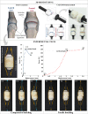
Upper part: Lateral and frontal views of the fingers’ joint anatomy pointing out the two characteristic (strong and weak) curvatures of the articulating bone terminals (Left) are compared with the CAD model and 3D-printed prototype of the finger bone-joint-bone system (Right). Central part: Assembled prototype employed for experimental tests—equipped with an articular capsule obtained from sow intestine, lubricating grease at the joint interface and ligament-like elastic bands—(Left) produces the compressive (blue) and tensile (red) force-displacement curves (Right). Lower part: Sequences of images showing the buckling kinematics exhibited by the system during the compressive (frames C1–C3) and tensile (frames T1–T3) tests; in particular, frames C1 and T1 correspond to initial (unloaded and undeformed) configurations, frames C2 and T2 show states immediately following the onset of equilibrium bifurcation and frames C3 and T3 provide configurations reached in the post-buckling phase. It is worth noticing that, due to the partial compressibility of the grease layer at the interface, the response in compression does not recover the infinitely rigid behavior theoretically predicted. Also, consistently with the anatomy of the finger joints and the theoretical model, elastic bands were positioned laterally in the sagittal and frontal planes and are shown in the photos deformed under compression or tension.

References

    1. Gray H., Anatomy of the Human Body (Philadelphia Lea and Febiger, ed. 20, 1918).
    1. Brocato M., Podio-Guidugli P., A bone-wise approach for modeling the human hind-midfoot. Part i: Kinematics. Meccanica 57, 977–998 (2022).
    1. Gray J., How Animals Move (Cambridge University Press, 1953).
    1. Ralphs J., Benjamin M., The joint capsule: Structure, composition, ageing and disease. J. Anat. 184, 503 (1994). - PMC - PubMed
    1. Mow V. C., Ateshian G. A., Spilker R. L., Biomechanics of diarthrodial joints: A review of twenty years of progress. J. Biomech. Eng. 115, 460–467 (1993). - PubMed

Publication types

LinkOut - more resources