. 2023 Oct 24;13(1):18141.
doi: 10.1038/s41598-023-45429-0.

A surface treatment method for improving the attachment of PDMS: acoustofluidics as a case study

Affiliations

A surface treatment method for improving the attachment of PDMS: acoustofluidics as a case study

Abdulla Al-Ali et al. Sci Rep. .

Abstract

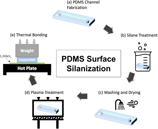
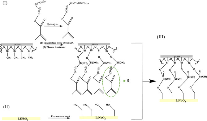
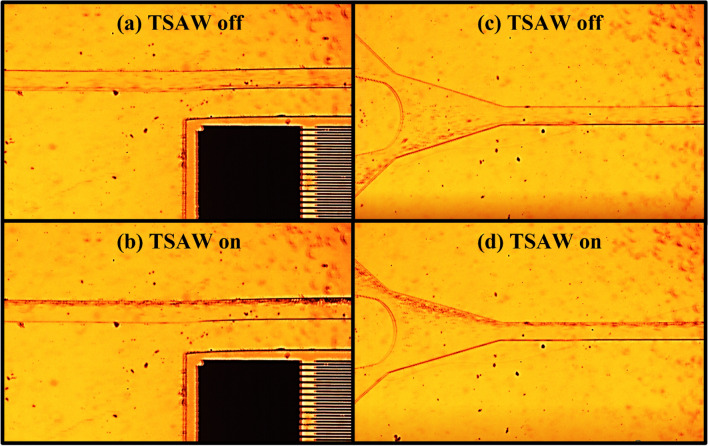
A method for a permanent surface modification of polydimethylsiloxane (PDMS) is presented. A case study on the attachment of PDMS and the lithium niobate (LiNbO3) wafer for acoustofluidics applications is presented as well. The method includes a protocol for chemically treating the surface of PDMS to strengthen its bond with the LiNbO3 surface. The PDMS surface is modified using the 3-(trimethoxysilyl) propyl methacrylate (TMSPMA) silane reagent. The effect of silane treatment on the hydrophilicity, morphology, adhesion strength to LiNbO3, and surface energy of PDMS is investigated. The results demonstrated that the silane treatment permanently increases the hydrophilicity of PDMS and significantly alters its morphology. The bonding strength between PDMS and LiNbO3increased with the duration of the silane treatment, reaching a maximum of approximately 500 kPa. To illustrate the effectiveness of this method, an acoustofluidic device was tested, and the device demonstrated very promising enhanced bonding and sealing capabilities with particle manipulation at a flow rate of up to 1 L/h by means of traveling surface acoustic waves (TSAW). The device was reused multiple times with no fluid leakage or detachment issues. The utility of the presented PDMS surface modification method is not limited to acoustofluidics applications; it has the potential to be further investigated for applications in various scientific fields in the future.


Conflict of interest statement

The authors declare no competing interests.

Figures

Figure 1
Figure 1
The implementation protocol of PDMS surface treatment using TMSPA to change the surface properties of the PDMS through five steps, which are (a) PDMS channel fabrication, (b) silane treatment, (c) washing and drying, (d) plasma treatment, and (e) thermal bonding.
Figure 2
Figure 2
An AFM (lift) and microscopic (right) examination of three representative samples (a) S-0, (b) S-60, (c) S-180.
Figure 3
Figure 3
The RMS values chart that represents the surface height variation for the 6-representative samples.
Figure 4
Figure 4
Chart of the average contact angles of the wettability test conducted for the 6-representative samples.
Figure 5
Figure 5
An illustration of the difference in the contact angle of the treated sample (S-60) on the right side compared to the bare PDMS sample (S-0) on the left side.
Figure 6
Figure 6
FTIR-AR spectra of (left side) S-0, S-60 and S-60 treated with plasma, (right side) S-0, S-240 and S-240 treated with plasma.
Figure 7
Figure 7
Schematic representation of the proposed mechanism for the bonding of PDMS and LiNbO3. (I) Attachment of TMSPMA to PDMS through the bonding between OH groups of hydrolyzed TMSPMA and Si–CH3 groups in PDMS forming –Si–O–Si– bond. Formation of C–O and C=O due to the breaking of C=C bonds in TMSPMA after plasma treatment, while unhydrolyzed Si–OCH3 were transformed to Si–OH. (II) Generation of OH groups on LiNbO3 surface by activation with plasma. (III) Bonding of PDMS and LiNbO3 by the formation of a covalent bond via the condensation reaction between Si–OH groups on the PDMS surface and OH groups on the LiNbO3 surface.
Figure 8
Figure 8
Right side: schematic illustration of the tensile test setup. Left side: tensile testing machine loaded with one of our samples for tensile testing.
Figure 9
Figure 9
The applied force vs the elongation curve generated from the tensile test for the 6-representative samples during the bonding strength measurement.
Figure 10
Figure 10
A photo of the microchannel leakage testing conducted using colored deionized water and syringe pump. The tested channel consists of one inlet at the left side and two outlets at the right side.
Figure 11
Figure 11
Schematic illustration of the TSAW based particle manipulation platform. (a) TSAW off: particles are flowing everywhere along the channels width and leaving the channel from both outlets. (b) TSAW on: particles are pushed to the channel’s wall away from the IDT and particles are leaving the channel trough outlet B only.
Figure 12
Figure 12
PS particles manipulation experiment as observed under an inverted microscope. (a) The location is at the middle of the microfluidic device. The TSAW device is off. The PS particles are flowing everywhere along the width of the channel at flow rate of 1000 µL/h. (b) The location is at the middle of the microfluidic device. The TSAW device is on. The PS particles are pushed toward the opposite channel’s wall due to the acoustic radiation force. (c) The location is at the outlet of the microfluidic device. The TSAW device is off. The PS particles are exiting the channel through both outlets at flow rate of 1000 µL/h. (d) The location is at the outlet of the microfluidic device. The TSAW device is on. The PS particles are exiting from the upper outlet only because of the effect of the acoustic radiation force.

References

    1. Duffy DC, Cooper McDonald J, Schueller OJA, Whitesides GM. Rapid prototyping of microfluidic systems in poly(dimethylsiloxane) Anal. Chem. 1998;70:4974–4984. doi: 10.1021/ac980656z. - DOI - PubMed
    1. InêsMiranda AS, Sousa P, Ribeiro J, ElisabeteM S, Castanheira RL, Minas G. Properties and applications of PDMS for biomedical engineering: A review. J. Funct. Biomater. 2022;13:1–20. doi: 10.3390/jfb13010002. - DOI - PMC - PubMed
    1. Sivakumar R, Lee NY. Microfluidic device fabrication mediated by surface chemical bonding. Analyst. 2020;145:4096–4110. doi: 10.1039/D0AN00614A. - DOI - PubMed
    1. Liu Ke, Pan Gu, Hamaker K, Hugh Fan Z. Characterization of bonding between poly(dimethylsiloxane) and cyclic olefin copolymer using corona discharge induced grafting polymerization. J. Colloid Interface Sci. 2012;365:289–295. doi: 10.1016/j.jcis.2011.09.004. - DOI - PMC - PubMed
    1. Berthier J, Silberzan P. Microfluidics for Biotechnology. Artech House; 2009.