

An Unpowered Knee Exoskeleton for Walking Assistance and Energy Capture
- PMID: 37893249
- PMCID: PMC10608919
- DOI: 10.3390/mi14101812
An Unpowered Knee Exoskeleton for Walking Assistance and Energy Capture
Abstract
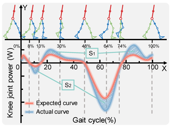
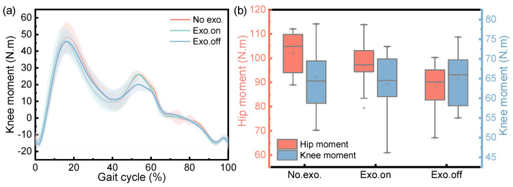
In order to reduce the energy consumption of human daily movement without providing additional power, we considered the biomechanical behavior of the knee during external impedance interactions. Based on the theory of human sports biomechanics, combined with the requirements of human-machine coupling motion consistency and coordination, an unpowered exoskeleton-assisted device for the knee joint is proposed in this paper. The effectiveness of this assisted device was verified using gait experiments and distributed plantar pressure tests with three modes: "not wearing exoskeleton" (No exo.), "wearing exoskeleton with assistance " (Exo. On), and "wearing exoskeleton without assistance" (Exo. Off). The experimental results indicate that (1) This device can effectively enhance the function of the knee, increasing the range of knee movement by 3.72% (p < 0.001). (2) In the early stages of the lower limb swing, this device reduces the activity of muscles in relation to the knee flexion, such as the rectus femoris, vastus lateralis, and soleus muscles. (3) For the first time, it was found that the movement length of the plantar pressure center was reduced by 6.57% (p = 0.027). This basic principle can be applied to assist the in-depth development of wearable devices.
Keywords: energy capture; energy compensation mechanism; knee joint; unpowered exoskeleton; walking assistance.
Conflict of interest statement
The authors declare no conflict of interest.
Figures


Similar articles
-
Modulating Multiarticular Energy during Human Walking and Running with an Unpowered Exoskeleton.Sensors (Basel). 2022 Nov 6;22(21):8539. doi: 10.3390/s22218539. Sensors (Basel). 2022. PMID: 36366237 Free PMC article.
-
Regulating Metabolic Energy Among Joints During Human Walking Using a Multiarticular Unpowered Exoskeleton.IEEE Trans Neural Syst Rehabil Eng. 2021;29:662-672. doi: 10.1109/TNSRE.2021.3065389. Epub 2021 Mar 22. IEEE Trans Neural Syst Rehabil Eng. 2021. PMID: 33690121
-
Reducing the metabolic energy of walking and running using an unpowered hip exoskeleton.J Neuroeng Rehabil. 2021 Jun 6;18(1):95. doi: 10.1186/s12984-021-00893-5. J Neuroeng Rehabil. 2021. PMID: 34092259 Free PMC article.
-
Contributions to the understanding of gait control.Dan Med J. 2014 Apr;61(4):B4823. Dan Med J. 2014. PMID: 24814597 Review.
-
A Wearable Lower Limb Exoskeleton: Reducing the Energy Cost of Human Movement.Micromachines (Basel). 2022 Jun 6;13(6):900. doi: 10.3390/mi13060900. Micromachines (Basel). 2022. PMID: 35744514 Free PMC article. Review.
Cited by
-
Research Status and Development Trend of Lower-Limb Squat-Assistant Wearable Devices.Biomimetics (Basel). 2025 Apr 22;10(5):258. doi: 10.3390/biomimetics10050258. Biomimetics (Basel). 2025. PMID: 40422089 Free PMC article. Review.
References
-
- Pont-Esteban D., Sánchez-Urán M.Á., Ferre M. Robust Motion control architecture for an upper-limb rehabilitation Exosuit. IEEE Access. 2022;10:113631–113648. doi: 10.1109/ACCESS.2022.3217528. - DOI
-
- Zhang Y., Bressel M., De Groof S., Domine F., Labey L., Peyrodie L. Design and control of a size-adjustable pediatric lower-limb exoskeleton based on weight shift. IEEE Access. 2023;11:6372–6384. doi: 10.1109/ACCESS.2023.3235654. - DOI
-
- Kwa H.K., Noorden J.H., Missel M., Craig T., Pratt J.E., Neuhaus P.D. Development of the IHMC mobility assist exoskeleton; Proceedings of the 2009 IEEE international conference on robotics and automation; Kobe, Japan. 12–17 May 2009; pp. 2556–2562.
-
- Zoss A.B., Kazerooni H., Chu A. Biomechanical design of the Berkeley lower extremity exoskeleton (BLEEX) IEEE/ASME Trans. Mechatron. 2006;11:128–138. doi: 10.1109/TMECH.2006.871087. - DOI
Grants and funding
LinkOut - more resources
Full Text Sources
