

High Isolation, Double-Clamped, Magnetoelectric Microelectromechanical Resonator Magnetometer
- PMID: 37896719
- PMCID: PMC10610584
- DOI: 10.3390/s23208626
High Isolation, Double-Clamped, Magnetoelectric Microelectromechanical Resonator Magnetometer
Abstract
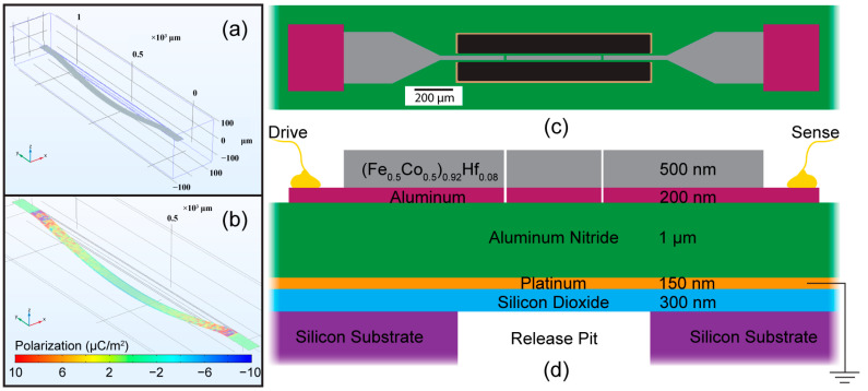
Magnetoelectric (ME)-based magnetometers have garnered much attention as they boast ultra-low-power systems with a small form factor and limit of detection in the tens of picotesla. The highly sensitive and low-power electric readout from the ME sensor makes them attractive for near DC and low-frequency AC magnetic fields as platforms for continuous magnetic signature monitoring. Among multiple configurations of the current ME magnetic sensors, most rely on exploiting the mechanically resonant characteristics of a released ME microelectromechanical system (MEMS) in a heterostructure device. Through optimizing the resonant device configuration, we design and fabricate a fixed-fixed resonant beam structure with high isolation compared to previous designs operating at ~800 nW of power comprised of piezoelectric aluminum nitride (AlN) and magnetostrictive (Co1-xFex)-based thin films that are less susceptible to vibration while providing similar characteristics to ME-MEMS cantilever devices. In this new design of double-clamped magnetoelectric MEMS resonators, we have also utilized thin films of a new iron-cobalt-hafnium alloy (Fe0.5Co0.5)0.92Hf0.08 that provides a low-stress, high magnetostrictive material with an amorphous crystalline structure and ultra-low magnetocrystalline anisotropy. Together, the improvements of this sensor design yield a magnetic field sensitivity of 125 Hz/mT when released in a compressive state. The overall detection limit of these sensors using an electric field drive and readout are presented, and noise sources are discussed. Based on these results, design parameters for future ME MEMS field sensors are discussed.
Keywords: aluminum nitride; iron cobalt hafnium; magnetoelectric; magnetometer; magnetostriction; mems.
Conflict of interest statement
The authors declare no conflict of interest.
Figures


References
-
- Khan M.A., Sun J., Li B., Przybysz A., Kosel J. Magnetic Sensors-A Review and Recent Technologies. Eng. Res. Express. 2021;3:022005. doi: 10.1088/2631-8695/ac0838. - DOI
-
- Lenz J.E. A Review of Magnetic Sensors. Proc. IEEE. 1990;78:973–989. doi: 10.1109/5.56910. - DOI
-
- Lenz J., Edelstein A.S. Magnetic Sensors and Their Applications. IEEE Sens. J. 2006;6:631–649. doi: 10.1109/JSEN.2006.874493. - DOI
-
- Ripka P. Review of Fluxgate Sensors. Sens. Actuators A Phys. 1992;33:129–141. doi: 10.1016/0924-4247(92)80159-Z. - DOI
-
- Gao J., Jiang Z., Zhang S., Mao Z., Shen Y., Chu Z. Review of Magnetoelectric Sensors. Actuators. 2021;10:109. doi: 10.3390/act10060109. - DOI
Grants and funding
LinkOut - more resources
Full Text Sources
Medical
Research Materials
Miscellaneous
