. 2023 Nov 9;13(1):19583.
doi: 10.1038/s41598-023-46101-3.

Swarm of lightsail nanosatellites for Solar System exploration

Affiliations

Swarm of lightsail nanosatellites for Solar System exploration

Giovanni Santi et al. Sci Rep. .

Abstract

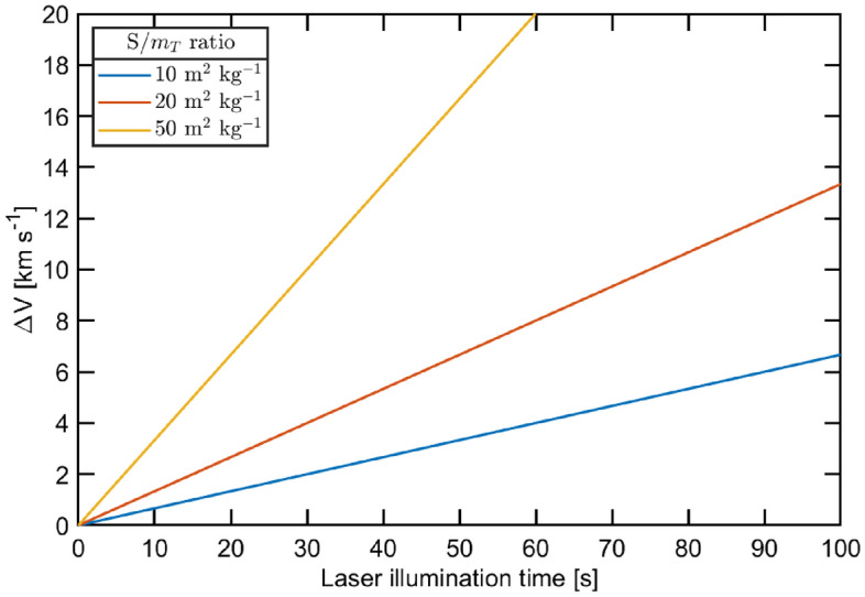
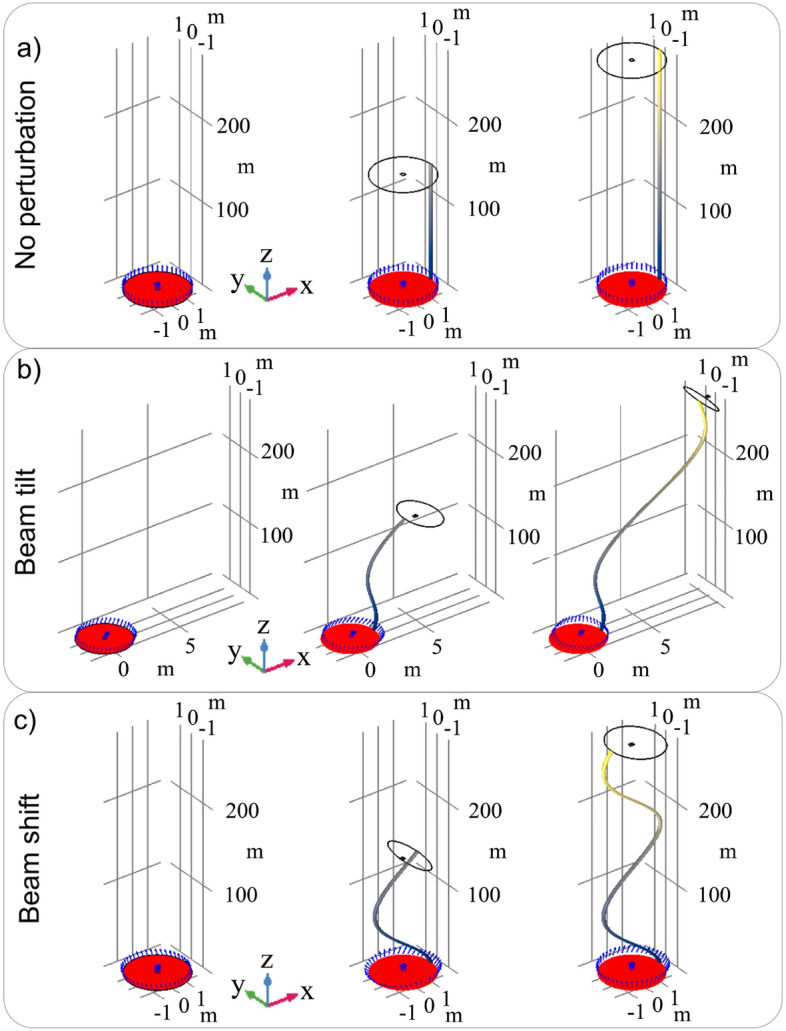
This paper presents a study for the realization of a space mission which employs nanosatellites driven by an external laser source impinging on an optimized lightsail, as a valuable technology to launch swarms of spacecrafts into the Solar System. Nanosatellites propelled by laser can be useful for heliosphere exploration and for planetary observation, if suitably equipped with sensors, or be adopted for the establishment of network systems when placed into specific orbits. By varying the area-to-mass ratio (i.e. the ratio between the sail area and the payload weight) and the laser power, it is possible to insert nanosatellites into different hyperbolic orbits with respect to Earth, thus reaching the target by means of controlled trajectories in a relatively short amount of time. A mission involving nanosatellites of the order of 1 kg of mass is envisioned, by describing all the on-board subsystems and satisfying all the requirements in terms of power and mass budget. Particular attention is paid to the telecommunication subsystem, which must offer all the necessary functionalities. To fabricate the lightsail, the thin films technology has been considered, by verifying the sail's thermal stability during the thrust phase. Moreover, the problem of mechanical stability of the lightsail has been tackled, showing that the distance between the ligthsail structure and the payload plays a pivotal role. Some potential applications of the proposed technology are discussed, such as the mapping of the heliospheric environment.


Conflict of interest statement

The authors declare no competing interests.

Figures

Figure 1
Figure 1
Concept of a swarm of nanosatellite propelled by laser.
Figure 2
Figure 2
Dependence of the velocity gain modulus ΔV from the laser illumination time for different S/mT values. The simulation assumes I0=1 GW m-2 and departure from a geostationary orbit.
Figure 3
Figure 3
Hyperbolic excess velocity for a tangential and a radial impulse. The simulation assumes an area to mass ratio (S/mT) equal to 10 m2 kg-1, I0=1 GW m-2 and departure from a geostationary orbit.
Figure 4
Figure 4
Porkchop plots of hyperbolic excess velocities v in the case of Earth departure in a 2033 launch window for Mars (left) and Venus (right). The curves of TOF reported are given in step of ten days and highlighted by the dashed grey lines.
Figure 5
Figure 5
Orbital transfers to Mars (left) and Venus (right) for the parameters reported in Table 1. The planets at departure and arrival are shown in full and faded colors, respectively. The portion of the orbits covered by the planet while the spacecraft is travelling into the interplanetary medium are reported in solid lines, and the remaining portion in dashed line.
Figure 6
Figure 6
(a) Schematic representation (not in scale) of the nanosatellite, comprising the lightsail (LS) and the payload (PL). (b) Temperature analysis for different laser powers P, being 10 MW, 100 MW, 1 GW and 10 GW, in the case d(PL)=50 cm. (c) Temperature analysis for P=10 GW varying the distance d(PL). (d) The maps (top panel) and the plot (bottom panel) report the deformations and the average rotation, respectively, occurring on the lightsail as function of the distance d(PL).
Figure 7
Figure 7
(a) Representative sketches (not in scale) of the beam tilt q, indicated in yellow. (a.1) Average rotation calculated by varying the laser power P, and q from 0.1×10⁻⁷ up to 1×10⁻⁷ rad. (b) Representative sketch (not in scale) of the source shift p illustrated in green. (b.1) Average rotation calculated by varying the laser power P and for p varying from 10 μm up to 10 mm. (c) Displacement map for beam tilt 1×10⁻⁷rad. (d) Displacement map for q=0.35×10⁻⁷ rad. (e) Displacement map for p=0.035 mm. (f) Displacement map for beam p=3.2 mm.
Figure 8
Figure 8
Numerical investigation of the lightsail trajectory; (a) the laser beam is nominal; (b) the laser beam is tilted of q=1×10⁻⁷ rad; (c) the beam is shifted of p=2.8 mm. For each result, the initial lightsail position is indicated by the solid red object, while the black wireframe and blue arrows indicate the new position and the velocity direction along the new trajectory (gray-yellow tube gradient) respectively. For all the case studies P=10 GW. Each reported panel uses the following axis scale factor: 2 along X and Y, and 0.1 along Z.

References

    1. Gong S, Macdonald M. Review on solar sail technology. Astrodynamics. 2019;3:93–125. doi: 10.1007/s42064-019-0038-x. - DOI
    1. Spröwitz, T. et al. Membrane deployment technology development at DLR for solar sails and large-scale photovoltaics. In 2019 IEEE Aerospace Conference, 1–20 (2019).
    1. Whorton, M., Heaton, A., Pinson, R., Laue, G. & Adams, C. L. Nanosail-D: The first flight demonstration of solar sails for nanosatellites. In 22nd Annual AIAA/USU Conference on Small Satellites (2008).
    1. http://sail.planetary.org/ Last access. 2019. http://sail.planetary.org/.
    1. Mori O, et al. First solar power sail demonstration by IKAROS. Trans. Jpn. Soc. Aeronaut. Space Sci. Aerosp. Technol. Jpn. 2010;8:To_4_25–To_4_31.