

A Frequency-Selective Reconfigurable Antenna for Wireless Applications in the S and C Bands
- PMID: 37960610
- PMCID: PMC10647608
- DOI: 10.3390/s23218912
A Frequency-Selective Reconfigurable Antenna for Wireless Applications in the S and C Bands
Abstract
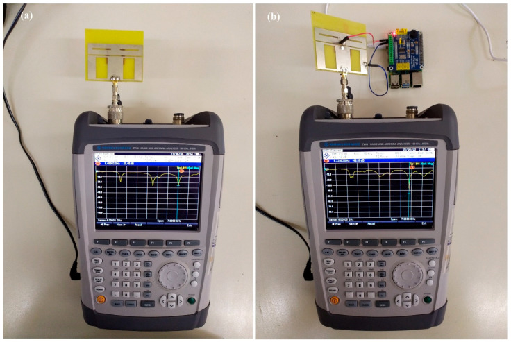
This paper presents a compact multifrequency reconfigurable patch antenna in terms of design and fabrication for operating in the S and C bands of the RF spectrum, which are overwhelmed by wireless applications. Reconfiguration is achieved by using a single PIN diode on the ground plane. By varying the voltage applied to the diode, three modes can emerge, exhibiting main resonant frequencies at 2.07, 4.63, and 6.22 GHz. Resonance switching requires a voltage of less than 0.9 V. The antenna fabricated on an FR-4 substrate, with a volume of 70 × 60 × 1.5 mm3, has a radiating patch element of a rectangular ring shape. The proposed low-cost antenna is easily implemented in a typical university lab-based environment. The total bandwidth for the three modes is close to 1 GHz, while the voltage standing wave ratio (VSWR) of the fabricated version of the antenna does not exceed 1.02, and the return loss is well below -40 dB for the three primary resonant frequencies.
Keywords: PIN diode; measurements; multifrequency; patch antenna; reconfigurable antenna.
Conflict of interest statement
The authors declare no conflict of interest.
Figures


References
-
- Mohanta H.C., Kouzani A.Z., Mandal S.K. Reconfigurable Antennas and Their Applications. Univers. J. Electr. Electron. Eng. 2019;6:239–258. doi: 10.13189/ujeee.2019.060406. - DOI
-
- Christodoulou C.G., Tawk Y., Lane S.A., Erwin S.R. Reconfigurable Antennas for Wireless and Space Applications. Proc. IEEE. 2012;100:2250–2261. doi: 10.1109/JPROC.2012.2188249. - DOI
-
- Parchin N.O., Basherlou H.J., Al-Yasir Y.I.A., Abdulkhaleq A.M., Abd-Alhameed R.A. Reconfigurable antennas: Switching techniques—A survey. Electronics. 2020;9:336. doi: 10.3390/electronics9020336. - DOI
-
- Costantine J., Tawk Y., Barbin S.E., Christodoulou C.G. Reconfigurable Antennas: Design and Applications. Proc. IEEE. 2015;103:424–437. doi: 10.1109/JPROC.2015.2396000. - DOI
-
- Ojaroudi Parchin N., Jahanbakhsh Basherlou H., Al-Yasir Y., Abd-Alhameed R., Abdulkhaleq A., Noras J. Recent Developments of Reconfigurable Antennas for Current and Future Wireless Communication Systems. Electronics. 2019;8:128. doi: 10.3390/electronics8020128. - DOI
LinkOut - more resources
Full Text Sources
Miscellaneous
