. 2023 Nov 18;14(1):7517.
doi: 10.1038/s41467-023-43390-0.

Simultaneous and independent topological control of identical microparticles in non-periodic energy landscapes

Affiliations

Simultaneous and independent topological control of identical microparticles in non-periodic energy landscapes

Nico C X Stuhlmüller et al. Nat Commun. .

Abstract

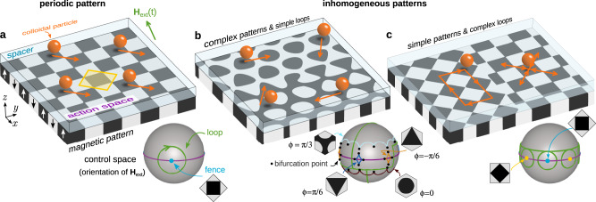
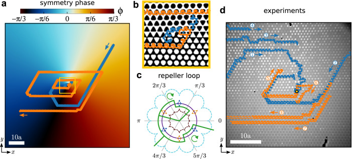
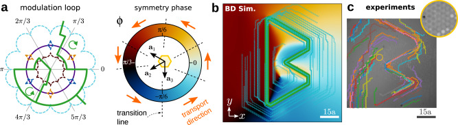
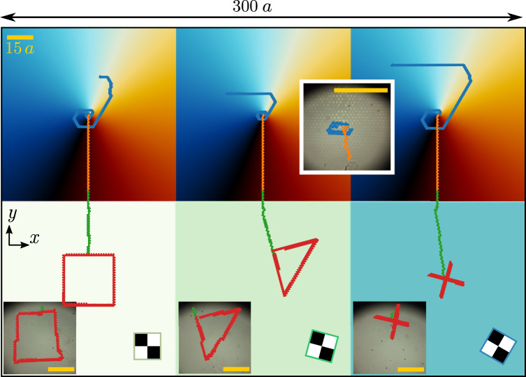
Topological protection ensures stability of information and particle transport against perturbations. We explore experimentally and computationally the topologically protected transport of magnetic colloids above spatially inhomogeneous magnetic patterns, revealing that transport complexity can be encoded in both the driving loop and the pattern. Complex patterns support intricate transport modes when the microparticles are subjected to simple time-periodic loops of a uniform magnetic field. We design a pattern featuring a topological defect that functions as an attractor or a repeller of microparticles, as well as a pattern that directs microparticles along a prescribed complex trajectory. Using simple patterns and complex loops, we simultaneously and independently control the motion of several identical microparticles differing only in their positions above the pattern. Combining complex patterns and complex loops we transport microparticles from unknown locations to predefined positions and then force them to follow arbitrarily complex trajectories concurrently. Our findings pave the way for new avenues in transport control and dynamic self-assembly in colloidal science.


Conflict of interest statement

The authors declare no competing interests.

Figures

Fig. 1
Fig. 1. Periodic vs inhomogeneous patterns.
a Periodic square pattern (a unit cell is highlighted in yellow), b hexagonal pattern in which the symmetry phase ϕ varies in space, and c a pattern made of two square patterns rotated by an angle of 45°. The patterns are made of regions with positive (black) and negative (white) magnetization normal to the pattern, see vertical arrows in (a). A polymer coating protects the patterns and acts as a spacer for the paramagnetic colloidal particles (orange) that are suspended in a solvent and move in a plane parallel to the pattern (action space). The motion is driven by a uniform external field (green arrow). The control space C (gray spheres) represents all possible orientations of the external field. The orientation of the external field varies in time performing a loop (green curves). Loops that wind around special orientations induce particle transport. These special orientations are determined by the position of the fences and bifurcation points in control space which depend on the local symmetry of the pattern. Shown are the fences of square patterns for one (a) and two (c) different orientations, as well as those of four hexagonal patterns with different symmetry phases ϕ (b). We also indicate the bifurcation points (black circles) in (b) which are those points where two fence segments meet. Next to the fences, we show the corresponding unit cell of the pattern. In periodic patterns (a) all the particles move in the same direction (orange arrows), independently of their position above the pattern. In inhomogeneous patterns, a single modulation loop can induce transport in different directions depending on the position of the particle above the pattern. Complex particle trajectories can be generated using complex patterns and simple loops (b) or simple patterns and complex loops (c).
Fig. 2
Fig. 2. Pattern with a topological defect.
a Magnetic pattern with a topological defect in the symmetry phase ϕ. The pattern is dissected into hexagonal cells (green hexagons). The central cell (yellow) contains the defect. Enlarged Wigner–Seitz cells of selected periodic hexagonal lattices with symmetry phase ϕ (see color bar) corresponding to their position in the pattern are shown. Next to each enlarged cell, we plot a stereographic projection of the corresponding control space and the modulation loop that attracts the particles toward the defect. Shown are the fences (blue), the equator (violet), and both the active (green) and the inactive (red) subloops. The loop winds as indicated by the circular black arrow. The two apparently open segments of the loop are actually joined at the south pole of the control space (not visible due to the projection). The transport direction (orange arrows) changes at the transition lines (black-dashed lines). b Illustrative configurations of the position of transition lines (black-dashed lines) that give rise to particle trajectories moving towards the defect (attractor) or away from it (repeller). The particle trajectories are illustrated in orange.
Fig. 3
Fig. 3. Attractor and repeller of particles.
a Trajectory of a colloidal particle (randomly initialized) obtained with Brownian dynamics simulations above a pattern with a central topological defect in the symmetry phase. The blue (orange) trajectory is generated by the repetition of the attractor (repeller) modulation loop that moves particles towards (away from) the defect. The pattern is colored according to the value of the symmetry phase (color bar). The scale bar is 10a. b Close-up of the region indicated by a yellow square in (a) and the trajectories around the central defect. The background shows the local magnetization of the pattern. c Stereographic projection of the repeller loop (green) in C. The equator (violet circle) and the fences of the C6 and S6 patterns as well as their inverse patterns, C6¯ and S6¯, (dashed curves) are also depicted as a reference. The fences are colored according to the value of the symmetry phase. The two apparently open segments of the loop are actually joined at the south pole of the control space (not visible due to the projection). The loop is made of two subloops winding clockwise, as indicated by the circular arrows. d Experimental trajectories of several colloidal particles (labeled with a numbered circle) above the same pattern with a topological defect (yellow circle). The trajectories induced by the attractor (repeller) loop are colored in blue (orange). Blue and orange trajectories correspond to different experiments and have been superimposed in the figure. Note that under the microscope regions with negative magnetization appear darker than regions with positive magnetization, i.e. the opposite of our color choice in e.g. (b). The scale bar is 10a and the lattice constant of one cell is approx. 14 μm. Movies of the simulated and the experimental motion are provided in Supplementary Movie 1.
Fig. 4
Fig. 4. Symmetry phase modulated pattern.
a Stereographic projection of control space showing the equator (violet circle), the closed modulation loop (green-solid curve), and the fences of patterns with C6, S6, C6¯ and S6¯ symmetries (dashed curves). The two apparently open segments of the loop are actually joined at the south pole of the control space (not visible due to the projection). The fences are colored according to the value of the symmetry phase (see the annular color bar). The transport directions induced by the loop (orange arrows) change at specific values of the symmetry phase ϕ as indicated by the transition lines (black-dashed lines). b Symmetry phase modulated pattern (the color indicates the value of the symmetry phase). A global rotation, ψ = π/2 in Eq. (6), makes one transport direction (lattice vector a3) parallel to the vertical axis. Particles above the pattern and subjected to the repetition of the modulation loop in (a) write the letter ''B''. Thin cyan lines show simulated particle trajectories for randomly initialized particles above the pattern. After several repetitions of the modulation loop, most particles enter the stable trajectory, highlighted with a thick green-solid line. c Experimental trajectories of colloidal particles above the pattern depicted in (b) and subjected to the modulation loop shown in (a). The region shown in the experiments (c) is smaller than that in simulations (b) due to the field of view of the microscope. The inset in (c) is a close view of the region indicated with a yellow circle in which we have altered the contrast of the image to better visualize the magnetization. Under the microscope regions with negative magnetization appear darker than those with positive magnetization. A colloidal particle (black dot) is also visible in the inset. A movie of the motion in simulations and experiments is provided in Supplementary Movie 2.
Fig. 5
Fig. 5. Simple patterns and complex loops.
a Five square magnetic patterns (and their corresponding control spaces) with a different value of the global orientation ψ, as indicated. The fences in C (blue circles) are four points located on the equator (violet circle). The position of the fences depends on the value of ψ. The modulation loop consists of four interconnected subloops that wind counterclockwise. A subloop is active (green) if it winds around a fence point (blue circles) and inactive (red) otherwise. The orange segments of the modulation loop simply connect the different subloops. Depending on the value of ψ, the modulation loop induces different transport directions (green arrows) or no transport at all. b A pattern made of 18 patches with square symmetry and different global orientation ψ (color bar). A modulation loop controls the trajectories of particles above each patch simultaneously and independently. The particle trajectories (black) write the first 18 letters of the alphabet. The length of the scale bar is 10a. A movie can be found in Supplementary Movie 3. c Experimental trajectories of colloidal particles above four square patches rotated with respect to each other. A schematic unit cell illustrating the global orientation is depicted in each patch. The length of the scale bar is 5a and in this case, we use patterns with a = 7 μm. A unique modulation loop transports the four colloidal particles simultaneously. The trajectories are colored according to the time evolution from blue (initial time) to red (final time). A movie showing the whole time evolution and a one-to-one comparison with computer simulations is available in Supplementary Movie 4.
Fig. 6
Fig. 6. Complex patterns and complex loops.
Brownian dynamics simulations of the transport of colloidal particles above a complex pattern made of three patches, each one with a topological defect in the symmetry phase (top) connected to three patches with square symmetry (down) rotated with respect to each other. The color of the patches with topological defects indicates the value of the symmetry phase ϕ. The color of the square patches indicates the global rotation ψ, illustrated with a sketch of the magnetization. A unique complex modulation loop made of four parts drives the transport in the whole system. In the first part, the repetition of the attractor loop moves the particles toward the defects (blue trajectories) and lets them wait there. The second part of the loop moves the particles downwards through the patterns with defects (orange trajectories). The third part of the loop moves the particles downwards in the square patterns (green trajectories). The last part of the loop writes a custom trajectory (square, triangle, and cross) depending on the global orientation ψ of the pattern (red trajectories). Insets show the corresponding experimental trajectories. The length of the scale bars (yellow) is 15a.

References

    1. Royall CP, Dzubiella J, Schmidt M, van Blaaderen A. Nonequilibrium sedimentation of colloids on the particle scale. Phys. Rev. Lett. 2007;98:188304. - PubMed
    1. Yang L, Alexandridis P. Physicochemical aspects of drug delivery and release from polymer-based colloids. Curr. Opin. Colloid Interface Sci. 2000;5:132–143.
    1. Boyd BJ. Past and future evolution in colloidal drug delivery systems. Expert Opin. Drug Deliv. 2007;5:69–85. - PubMed
    1. Beija M, Salvayre R, de Viguerie NL, Marty J-D. Colloidal systems for drug delivery: from design to therapy. Trends Biotechnol. 2012;30:485–496. - PubMed
    1. McGorty R, Fung J, Kaz D, Manoharan VN. Colloidal self-assembly at an interface. Mater. Today. 2010;13:34–42.