. 2023 Oct:139:101173.
doi: 10.1016/j.pmatsci.2023.101173. Epub 2023 Jul 26.

Strategies for Development of Synthetic Heart Valve Tissue Engineering Scaffolds

Affiliations

Strategies for Development of Synthetic Heart Valve Tissue Engineering Scaffolds

Yuriy Snyder et al. Prog Mater Sci. 2023 Oct.

Abstract

The current clinical solutions, including mechanical and bioprosthetic valves for valvular heart diseases, are plagued by coagulation, calcification, nondurability, and the inability to grow with patients. The tissue engineering approach attempts to resolve these shortcomings by producing heart valve scaffolds that may deliver patients a life-long solution. Heart valve scaffolds serve as a three-dimensional support structure made of biocompatible materials that provide adequate porosity for cell infiltration, and nutrient and waste transport, sponsor cell adhesion, proliferation, and differentiation, and allow for extracellular matrix production that together contributes to the generation of functional neotissue. The foundation of successful heart valve tissue engineering is replicating native heart valve architecture, mechanics, and cellular attributes through appropriate biomaterials and scaffold designs. This article reviews biomaterials, the fabrication of heart valve scaffolds, and their in-vitro and in-vivo evaluations applied for heart valve tissue engineering.

Keywords: Heart valve; fiber; hydrogel; scaffold; solid porous; tissue engineering.


Figures

Figure 1.
Figure 1.
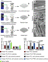
Overview of a heart valve structure. Schematic illustration of anatomical structures, hemodynamic flow, and the leaflet trilayer microstructure of heart valve (I). Movaťs Pentachrome stained histological images of trilayer leaflets of the human aortic valve (AV) (II) [25].
Figure 2.
Figure 2.
The schematic of heart valve scaffold designing and application for heart valve tissue engineering. Efficient scaffold design necessitates appropriate material properties, scaffold morphology, structure, geometry, and capability to bear physiological stress. Solid-porous, fibrous, or hydrogel heart valve scaffolds can be cellularized in static/dynamic conditions with patient-specific cells or tissue-engineered subcutaneously before being used as heart valve replacement.
Figure 3.
Figure 3.
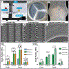
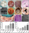
Microfabricated scaffold for heart valve tissue engineering. SEM image of PGS scaffold with an anisotropic honeycomb structure before (I) and after (II) tissue engineering. Its mechanical properties are represented by stress-strain curves (III) and a graphical chart (IV) with different curing times. The pore deformation profiles in the radial and circumferential directions are shown in a 2D finite element simulation (V) [123].
Figure 4.
Figure 4.
Solid-porous heart valve scaffolds produced through casting and molding methods. A multistep-injection mold (I) was applied to develop a fibrin-bilayer heart valve scaffold (placed in a pulse duplicator) (II). Cellularized leaflet scaffold with two distinct cell populations stained with Hoechst 33258 (blue) and calcein-AM (green) (III). The high magnification image of two distinct cell populations (IV) [46]. A schematic of a mold for producing fibrin heart valves for transcatheter implantation (V). Image of a plastic mold (VI) used to fabricate a fibrin scaffold with an adhered stent for transcatheter implantation (VII). The crimping of the scaffold (VIII) caused the smooth scaffold structure (IX) to become rough and damaged (X), as shown using SEM. Crimping the scaffold did not affect the amount of hydroxyproline produced in the scaffold after tissue engineering (XI) [85].
Figure 5.
Figure 5.
Electrospinning of trilayer PCL/PLCL or PCL/PTMC heart valve leaflets with highly anisotropic properties. The electrospinning of the circumferential (a), random (b), and radial layers (c) of trilayer PCL/PLCL substrates over a leaflet-shaped collector in chronological order (I) [132]. SEM images of circumferentially oriented (II) (shown by a double-headed arrow), randomly oriented (III), and radially oriented (IV) fibers (shown by a double-headed arrow) in the circumferential, random, and radial layers of the trilayer PCL/PLCL or PCL/PTMC substrates [133]. (V) The anisotropic ratios (circumferential/radial) of the tensile modulus and strength of trilayer PCL and PCL/PLCL substrates, cell-cultured constructs, and native leaflet tissue [132]. (VI) The anisotropic ratios (circumferential/radial) of the tensile modulus and strength of trilayer PCL and PCL/PTMC substrates and cell-cultured constructs [133].
Figure 6.
Figure 6.
Melt-electrowriting method applied for heart valve scaffold development. Utilizing voltage and heating in a melt electrowriting system produces a PCL fiber deposited onto a flat collector (I). The flat scaffold can be cut and sutured to form leaflets (II) and a heart valve conduit (III). The fibers can be deposited to form a flat (IV) or serpentine (V) microstructure with multiple fibers stacked over each other (VI). Graph depicting the mechanical properties of 15-, 20-, and 30-layer scaffolds (VII). Decreasing pore size increased the mechanical properties of the fibrous scaffolds (VIII) [65].
Figure 7.
Figure 7.
Melt-electrowriting for development of scaffold with specific morphologies. Images of the PCL fibers with circumferential (I), radial (II), and diagonal (III) orientations. Photo of the circumferential layer of the PCL-MMA flat scaffold (IV). 17 mm stent CAD design for mounting the flat PCL-MMA heart valve scaffold (V). The heart valve scaffold is mounted in the stent within a pulse duplicator (VI). Graphs show the scaffolds' UTS (VII) and elastic modulus (VIII) with circumferential, radial, and diagonal orientations [63].
Figure 8.
Figure 8.
Microfibrous JetValve scaffold is produced using a novel Rotary Jet Spinning system for transcatheter heart valve implantation. Collector modification for electrospinning JetValve scaffolds with sinus bulges (I). Example of the two-step mandrel collector system used for making JetValve scaffolds. The Rotary Jet Spinning system (III) consists of multiple motors, a fiber extrusion reservoir, and a collector system. Heart valve scaffold leaflet mold (IV) was applied to produce JetValve scaffold (V), which was crimped (VI) before implantation. The scaffold exhibited aligned fiber (VII). The scaffold was prepared for transcatheter implantation by mounting it to a self-expanding nitinol stent. The stented scaffold was deployed in the valvular position over the native leaflets. The radial pressure caused by the stent expanding held it in the desired positions within the pulmonary artery (VIII). The biaxial mechanical properties represented the stress-strain graph (IX) [54].
Figure 9.
Figure 9.
Electrospinning of trilayer PLGA/PASP heart valve leaflets with highly anisotropic properties. Schematic of the positive/negative conjugate electrospinning system with cospinning of PLGA and PASP over a drum collector (I). Schematic of bioactive PASP hydrogel formation (II). SEM images of the circumferential (III), random (IV), and radial layers (V) of the nanofibrous trilayer electrospun PLGA/PASP substrates. Elastic modulus and yield strengths of the trilayer electrospun PLGA, PLGA/PASP-L, PLGA/PASP-H substrates (VI) [147].
Figure 10.
Figure 10.
PC-UP heart valve scaffolds with aligned or random fiber orientations for a 12-month in vivo study. PC-UP heart valve scaffolds (I) with either aligned (II) or random fibers (III) are shown by SEM imaging. The aligned fibers increased the mechanical properties of the heart valve scaffolds (IV-V). The histogram shows the scaffold fibers’ orientation with angles of 0 (VI) and 90 (VII) degrees representing the circumferential and radial orientations, respectively [55].
Figure 11.
Figure 11.
3D bioprinting of heart valve scaffolds using different CAD designs, various molecular weight hydrogels, and several bioink ratios. Schematic of gel-extrusion bioprinting system (I) that produces crosslinked hydrogel scaffolds. PEG-DA hydrogel scaffolds were produced from a generalized model (II-III) or porcine heart valve anatomy (IV-V). SEM images showed differences in structure and porosity for scaffolds made from 700 MW (VI) or 8000 MW gels (VII). Scaffolds with higher molecular weight hydrogel exhibited higher mechanical properties (VIII-IX). There were geometric deviations between the scanned porcine aortic heart valve and leaflets, as shown by the heat map (X) [62].
Figure 12.
Figure 12.
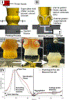
Sodium alginate hydrogel heart valve scaffold produced using printing and modeling processes. Schematic showing the printing process of the aortic valve sugar (sucrose and glucose) glass mold loaded with calcium chloride (I). Schematic showing the molding process of the aortic valve scaffold using mold-injection of a formulation containing sodium alginate loaded with GDL and calcium carbonate for internal gelation (II). Dissolution process of the sugar glass mold and image of the sodium alginate hydrogel heart valve scaffold (III). The average measured flow rate at 60 BPM in a custom-made cardiac bioreactor on three averaged aortic valve scaffolds compared to the physiological value curves (IV).
Figure 13.
Figure 13.
Summary of the current advances in self-assembling tissue-engineered heart valves utilizing tissue sheets or different molds. Image of the tissue sheet after 7 weeks of growth (I) and after cutting out leaflet sections (II). The leaflet sections (III) were mounted in a metal support stent forming a heart valve (IV). Masson’s trichrome-stained tissue sections show a multilayer structure (V) [201]. Image of the stainless-steel mold and Delrin inserts used for growing the tissue sheets (VI). Main template chamber before and after the growth of the multilayer tissue sheet (VII). Image of the process for wrapping the 8-layer leaflet-shaped tissue sheet into a cylindrical shape with the stainless-steel collector (VIII). The complete heart valve is held together with LigaClips before the final culture (IX) [206]. 23 mm diameter cylindrical mold used to wrap self-assembled sheets to form a conduit for a heart valve (X). Self-assembled leaflet sections were mounted on the inside of the conduit forming a heart valve. Images show the valve from the proximal (XI) and distal (XII) directions. The tissue section with F-actin labeling shows the formation of a cytoskeleton and tissue alignment after bioreactor treatment (XIII) [202].
Figure 14.
Figure 14.
Autologous heart valve scaffold grown in ovine subcutaneous space using a mold. Silicon mold (I) and an in vivo tissue-engineered valve scaffold (II) were grown over the mold. Tissue-engineered valve leaflets are shown from the distal side (III) and the tissue scaffold's luminal surface (IV). H&E-stained leaflet and conduit section before implantation (V). Leaflet sections stained with H&E, Masson's trichrome, and Van Gieson stains before implantation (VI). H&E-stained leaflet and conduit section (VII) and leaflet sections stained with H&E, Masson’s trichrome, and Van Gieson after implantation (VIII) [211].
Figure 15.
Figure 15.
Overview of the different types of in silico studies analyzing fluid dynamics, leaflet geometries, and biomechanics. Image of a patient-specific valve geometry design. The blue points and red lines specify the attachment points between the leaflets and root and boundaries, respectively (I). The velocity field of the valve is produced using an FSI model in the open positions (II) [234]. FSI results show the asymmetric flow distribution through the valve at a bulk velocity (Re=6000) over time [227]. Gross images of tissue-engineered heart valve from the proximal (IV) position used for a coupled in vivo and in silico study. Radial (V) and circumferential (VI) strain distributions of four different valve geometries during hemodynamic loading. Graphs comparing the actual and predicated collagen volume in the leaflets for the four-valve geometries (VII) [108].
Figure 16.
Figure 16.
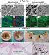
Summary of the effects of pore size/porosity and calcification. a) SEM images comparing large- (I) and small-diameter (II) fiber scaffolds. Confocal 3D images show scaffold cellularization and actin expression in scaffolds with large (III) and small fibers (IV) [272]. SEM images depict hydrogels with large (V) and small pore sizes (VI). After tissue engineering, fluorescent imaging showed deeper cell infiltration in large pore scaffolds (VII), while small pore scaffolds had extensive cellularization of their surface (VIII) [273]. b) Calcified heart valve with retraction (I) and leaflet fusion (II) – its dissected form (III). Von Kossa staining images at low (IV) and high (V) magnification of the leaflets show calcium nodules in the valve [55, 274].
Figure 17.
Figure 17.
Summary of the mechanism of leaflet retraction and the expression of α-SMA and SM22. Cellular signaling pathway for fibroblast activation to myofibroblast and smooth muscle cell (I). Immunocytochemistry of aortic (II-III) and pulmonary (IV-V) valve leaflets showing α-SMA and SM22 expression in the ventricularis region. The expression of these signals is greater in the aortic valve than in the pulmonary valve [281].
Figure 18.
Figure 18.
Summary of thrombosis on synthetic heart valve scaffolds. Schematic showing the thrombosis pathway for blood-contacting biomaterials (I). An example of a thrombotic heart valve (II).
Figure 19.
Figure 19.
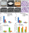
In vitro testing of a trilayer heart valve scaffold produced on a wheel-and-spoke collector. Nanofibrous flat, trilayered PCL leaflet scaffold before (I) and after (II) tissue engineering. SEM images show the alignment of VICs (III-IV) and collagen fibrils (V-VI) on the circumferential and radial fibrosa sides of the scaffold after tissue engineering in static conditions. Masson’s trichrome shows tissue alignment on both sides of the scaffold (VII-VIII). Graph depicting the survivability of VICs seeded onto the scaffolds over 14 days (IX). Graph showing the number of cells on the trilayer substrate over 14 days (X). Graph comparing the expression of α-SMA, vimentin, and collagen type I between trilayer substrates and native leaflet tissue (XI) [4].
Figure 20.
Figure 20.
In vitro tissue engineering of heart valve scaffolds made of PCL, PLLA, PCL/PLLA blends, and mixtures. a) Co-spun or composite PCL/PLLA heart valve scaffolds (I) with a microfiber structure (II) were mounted to a silicon holder (III) and placed in a bioreactor (IV) for tissue engineering. The immunofluorescence images of the tissue-engineered valves exhibit actin formation, primarily in the ventricularis (V). Their high-magnification images – co-spun valve (VI) and blended valve (VII). The mechanical properties of scaffolds made of individual and composite polymers are represented by stress-strain curves (VIII) and graphical charts (IX) [78].
Figure 21.
Figure 21.
In-vitro tissue engineering with fibrin valve scaffold in static and dynamic conditions. Gross appearance of fibrin-based tissue-engineered heart valve conditioned in a bioreactor – with opened leaflets (I) and closed leaflets (II). Histological images of native heart valve conduit wall (III) and leaflet (IV). Tissue-engineered conduit wall (V) and leaflet (VI) under stirring conditions. Bioreactor conditioned tissue-engineered conduit wall (VII) and leaflet (VIII) [85].
Figure 22.
Figure 22.
Heart valve scaffolds with random or aligned fibers were tissue-engineered for 12-months in an ovine model. PC-UP heart valve leaflet scaffolds are made of random (I) and aligned fiber (II) separately—their tissue-engineered heart valves (III) and (IV), respectively, in an ovine model. Leaflet retraction was more prevalent in aligned fiber scaffolds. Their tissue-engineered leaflets stained with H&E exhibited neotissue formation (V-VI). Leaflet sections stained with picrosirius red indicated collagen fiber formation, but the tissue did not resemble the aligned (VII) and randomly (VIII) orients from the original scaffolds after 12-month implantation. The aligned fiber leaflet scaffolds were initially anisotropic, but after 12 months in vivo, they no longer exhibited this property (IX). Biochemical analysis showed increases in the DNA content of the scaffolds throughout the in vivo study (X) [55].
Figure 23.
Figure 23.
PGA heart valve scaffolds that are first tissue-engineered in vitro, subsequently decellularized, and then implanted into the ovine model using a transcatheter system. PGA heart valve scaffold mounted in a stent (I) was tissue-engineered in-vitro - top view (II) and side view (III). H&E staining of the leaflet indicated dense tissue formation, mainly in the ventricularis (IV). The scaffolds were decellularized and implanted in vivo using a transcatheter system (V). The tissue-engineered constructs are shown after 4 hours (VI), eight weeks (VII), and 24 weeks (VIII) of in vivo tissue engineering. The leaflets show damage at the free edge and tissue retraction after 24 weeks (IX). H&E-stained leaflet sections (X) show scaffold cellularization and SEM images exhibit endothelial formation after the 24-week implantation (XI). The graphs depict DNA (XII) and GAG (XIII) quantities within the tissue over the 24-week in vivo study [145, 348].
Figure 24.
Figure 24.
Trilayer heart valve scaffolds showing conservation of scaffold structure after in vivo tissue engineering. Leaflet-shaped collector (I) was applied to fabricate a trilayer leaflet scaffold (II), which was then applied for tissue engineering (III). SEM images show the scaffold layers with a circumferentially oriented fibrosa (IV), a randomly oriented spongiosa (V), and a radially oriented ventricularis (VI). Iťs H&E-stained circumferential (VII) and radial (VIII) cross-sectional images exhibited circumferential (CL), random (RM), and radial (RL) layers with respective orientations. The graphs depict the mechanical properties of the leaflet scaffolds, leaflet constructs, and controls in the circumferential (IX) and radial directions (X). Results of immunohistology for vimentin and α-SMA of native leaflets and the tissue-engineered constructs (XI). Protein quantification results for collagen, GAG, and elastin of native leaflets and the tissue-engineered constructs (XII) [57].

Similar articles

Cited by

References

    1. Coffey S, Roberts-Thomson R, Brown A, Carapetis J, Chen M, Enriquez-Sarano M, et al. Global epidemiology of valvular heart disease. Nature Reviews Cardiology. 2021;18:853–64 - PubMed
    1. Snyder Y, Jana S. Strategies for development of decellularized heart valve scaffolds for tissue engineering. Biomaterials. 2022;288:121675. - PubMed
    1. Verstraete A, Herregods M-C, Verbrugghe P, Lamberigts M, Vanassche T, Meyns B, et al. Antithrombotic treatment after surgical and transcatheter heart valve repair and replacement. Frontiers in Cardiovascular Medicine. 2021;8:835. - PMC - PubMed
    1. Jana S, Lerman A. Behavior of valvular interstitial cells on trilayered nanofibrous substrate mimicking morphologies of heart valve leaflet. Acta biomaterialia. 2019;85:142–56. - PMC - PubMed
    1. Carrel T, Dembitsky WP, de Mol B, Obrist D, Dreyfus G, Meuris B, et al. Non-physiologic closing of bi-leaflet mechanical heart prostheses requires a new tri-leaflet valve design. International journal of cardiology. 2020;304:125–7. - PubMed

LinkOut - more resources