. 2023 Nov 24;14(1):7716.
doi: 10.1038/s41467-023-42866-3.

Synchronous micromechanically resonant programmable photonic circuits

Affiliations

Synchronous micromechanically resonant programmable photonic circuits

Mark Dong et al. Nat Commun. .

Abstract

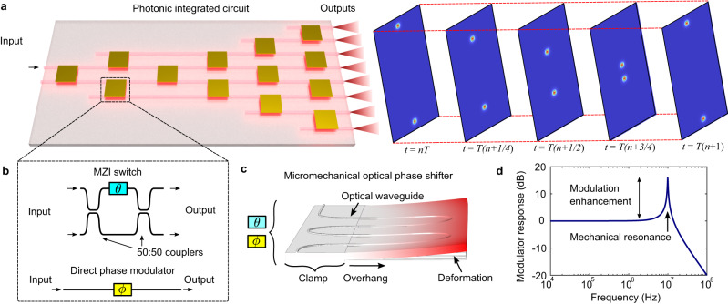
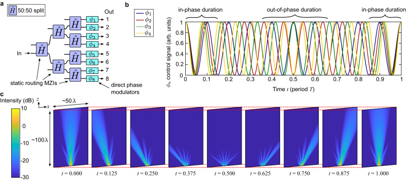
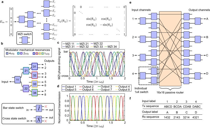
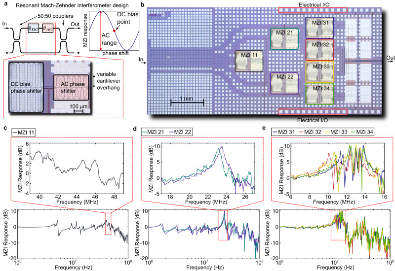
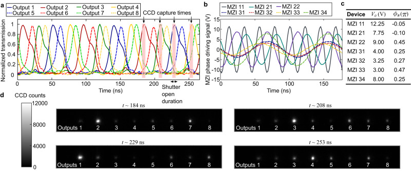
Programmable photonic integrated circuits (PICs) are emerging as powerful tools for control of light, with applications in quantum information processing, optical range finding, and artificial intelligence. Low-power implementations of these PICs involve micromechanical structures driven capacitively or piezoelectrically but are often limited in modulation bandwidth by mechanical resonances and high operating voltages. Here we introduce a synchronous, micromechanically resonant design architecture for programmable PICs and a proof-of-principle 1×8 photonic switch using piezoelectric optical phase shifters. Our design purposefully exploits high-frequency mechanical resonances and optically broadband components for larger modulation responses on the order of the mechanical quality factor Qm while maintaining fast switching speeds. We experimentally show switching cycles of all 8 channels spaced by approximately 11 ns and operating at 4.6 dB average modulation enhancement. Future advances in micromechanical devices with high Qm, which can exceed 10000, should enable an improved series of low-voltage and high-speed programmable PICs.


Conflict of interest statement

D.E. is a Scientific Advisor to and holds shares in QuEra Computing. The other authors declare no competing interests.

Figures

Fig. 1
Fig. 1. Micromechanically resonant programmable photonic integrated circuits.
a Schematic render of a programmable photonic integrated circuit actuated with only periodic sinusoidal driving signals. The optical output channels switch periodically in time, as illustrated by the time stamps t = nTt = T(n + 1). b Diagram of circuit components, consisting of Mach-Zehnder interferometer (MZI) switches and direct phase modulators with reconfigurable phases θ and ϕ respectively. c Finite-element render of a micromechanical optical phase shifter implemented as a piezo-actuated cantilever. d Theoretical modulator response and enhancement (Eq. 3) of a phase shifter with a single mechanical resonance where ω0 = 10 MHz and Qm= 40.
Fig. 2
Fig. 2. Resonantly actuated 8-channel phased array.
a Architecture of a photonic integrated circuit (PIC) phased array based on 8 optical outputs consisting of static MZIs for power routing and direct phase modulators at the output of each channel. These modulators offset each channel’s phase by a steady rate over time, defined by the frequency difference NΔω. b Example plots of the control signals applied to the first four channels ϕ1ϕ4. The channels periodically drift in and out of phase on a timescale defined by T=2π/Δω. c Gaussian beam calculations of the 8 output phased array at discrete times over a spatial domain of 50λ × 100λ of the x and z axes, respectively. The central beam combines constructively when all control phases ϕn are in phase (t = 0). At subsequent times, the beam sweeps counterclockwise and repeats at every t = T.
Fig. 3
Fig. 3. Architecture of micromechanically resonant 1 × N and N × N integrated optical switches.
a Schematic of a general 1 × N optical switch implemented as a binary tree mesh of Mach-Zehnder interferometers (MZIs) with transfer function Tij. b Design of a resonantly actuated 1 × 8 optical switch operating at three distinct frequencies, each unique to a column of MZIs. c Examples of driving signals in time domain to each of the MZIs with appropriate phase offsets. Each signal oscillates between bar and cross switching states. d Theoretical normalized optical intensity of the 8 output channels plotted in time domain when the circuit in (b) is driven with the signals in (c). e Schematic of a resonantly actuated 4 × 4 matrix switch consisting of 8 individual 1 × 4 switches connected through a 16 × 16 passive router. The individual switches are programmed with different driving signals to facilitate a proper switching order. f Example periodic transmission and receiving pattern through the 4 × 4 matrix switch.
Fig. 4
Fig. 4. Design and characterization of a piezoelectric 1 × 8 integrated optical switch.
a Illustration of the resonantly actuated Mach-Zehnder interferometer (MZI) design with two independent phase shifters: one larger, non-resonant cantilever for static DC biasing to the midpoint of the MZI’s sinusoidal response function and one smaller, AC cantilever designed with a target mechanical eigenfrequency. b Optical microscope image of the fully fabricated PIC with labeled MZIs, optical inputs and outputs, and electrical bonding pads. ce Measured small-signal response of the AC cantilever for the first (MZI 11), second (MZI 21 and 22) and third (MZI 31, 32, 33, and 34) columns, respectively—each measured trace is averaged 100x. In this device, the targeted base frequency is nominally 10 MHz; zoomed-in plots show the response near 40, 20, and 10 MHz, respectively.
Fig. 5
Fig. 5. Measurements of the 8-channel full switching sequence.
a Time-resolved measurements of all 8 optical outputs during a full switching sequence with a base frequency of 11.3 MHz for three full periods. Charged-coupled device (CCD) capture times for the imaging experiment in (d) are also labeled, depicting the small integration region defined by the camera shutter. b Plots of the sinusoidal driving inputs to the all seven Mach–Zehnder interferometers (MZIs). c Table of driving parameters, including voltage amplitude V0 and phase ϕs. The driving phase term compensates for the variation in each cantilever’s phase response. d CCD images captured at various times t as labeled in (a). Each image integrates the output from all 8 optical channels for 4.8 ns and illustrates an unnormalized snapshot of the output at different temporal offsets in the total switching sequence.

References

    1. Bogaerts W, et al. Programmable photonic circuits. Nature. 2020;586:207–216. doi: 10.1038/s41586-020-2764-0. - DOI - PubMed
    1. Pérez D, Gasulla I, Das Mahapatra P, Capmany J. Principles, fundamentals, and applications of programmable integrated photonics. Adv. Opt. Photonics. 2020;12:709. doi: 10.1364/AOP.387155. - DOI
    1. Carolan J, et al. Universal linear optics. Science. 2015;349:711–716. doi: 10.1126/science.aab3642. - DOI - PubMed
    1. Xu X, et al. Self-calibrating programmable photonic integrated circuits. Nat. Photonics. 2022;16:595–602. doi: 10.1038/s41566-022-01020-z. - DOI
    1. Tang R, Tanomura R, Tanemura T, Nakano Y. Ten-port unitary optical processor on a silicon photonic chip. ACS Photonics. 2021;8:2074–2080. doi: 10.1021/acsphotonics.1c00419. - DOI