. 2023 Nov 9;15(22):5352.
doi: 10.3390/cancers15225352.

Towards Realistic 3D Models of Tumor Vascular Networks

Affiliations

Towards Realistic 3D Models of Tumor Vascular Networks

Max C Lindemann et al. Cancers (Basel). .

Abstract

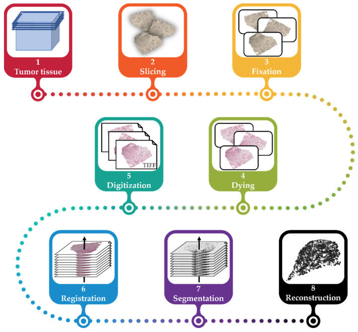
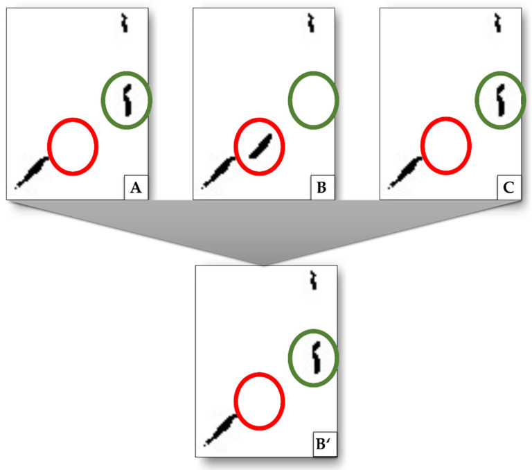
For reliable in silico or in vitro investigations in, for example, biosensing and drug delivery applications, accurate models of tumor vascular networks down to the capillary size are essential. Compared to images acquired with conventional medical imaging techniques, digitalized histological tumor slices have a higher resolution, enabling the delineation of capillaries. Volume rendering procedures can then be used to generate a 3D model. However, the preparation of such slices leads to misalignments in relative slice orientation between consecutive slices. Thus, image registration algorithms are necessary to re-align the slices. Here, we present an algorithm for the registration and reconstruction of a vascular network from histologic slices applied to 169 tumor slices. The registration includes two steps. First, consecutive images are incrementally pre-aligned using feature- and area-based transformations. Second, using the previous transformations, parallel registration for all images is enabled. Combining intensity- and color-based thresholds along with heuristic analysis, vascular structures are segmented. A 3D interpolation technique is used for volume rendering. This results in a 3D vascular network with approximately 400-450 vessels with diameters down to 25-30 µm. A delineation of vessel structures with close distance was limited in areas of high structural density. Improvement can be achieved by using images with higher resolution and or machine learning techniques.

Keywords: histologic images; image processing; image registration; reconstruction; segmentation; tumor; vascular network model.


Conflict of interest statement

The authors declare no conflict of interest. The funders had no role in the design of the study; in the collection, analyses, or interpretation of data; in the writing of the manuscript, or in the decision to publish the results.

Figures

Figure 1
Figure 1
The general workflow for the reconstruction of the vascular network. The tumor tissue is explanted and embedded in paraffin wax (1), sliced into 2.5 µm slices (2), fixated in 3.5% formaldehyde, and placed on slides (3). The tissue on each slide is then immunohistochemically stained (4) and then digitized (5). The resulting images are registered (6). Using segmentation, vascular structures are extracted (7) and reconstructed for the vascular model of the initial tumor (8).
Figure 2
Figure 2
Tumor slice immunohistochemically stained. (A) Vessels with clear outlines and homogeneous interiors. (B) Vessels with clear outline and perturbed interiors. (C) Vessels with perturbed outlines and no interiors. (D) Stained cell nuclei.
Figure 3
Figure 3
The registration proceeds in two steps. In the first step, each image is aligned to the previous one (i.e., 2 to 1, 3 to 2, etc.). Each of these registrations yield a transformation that can be saved to file (A, B, etc.). In the second step, each image is aligned to the first one in the set using concatenations of the transformations saved in the first step. All calculations within a step are performed in parallel.
Figure 4
Figure 4
Results of segmentation steps for two image excerpts 1 and 2. (A) shows excerpts with one vascular structure each. (1A) has a well-defined contour with a perturbed interior, whereas (2A) has a clear interior with a perturbed contour. (B) shows the results of extracted interiors of vessels, and (C) shows the results of their extracted contours. (D) is a fusion of (B) and (C), indicating significant differences in possibly detected interiors and contours (white spaces between interior and contours). (E) shows the result of the segmentation after dilating and filling the detected vessels to their contours (see step (v)). Images (F) show the final segmentation results with applied smoothing.
Figure 5
Figure 5
Exemplary procedure to remove structures that are related to damage artifacts and not to vessels as well as to add missing structures by interpolation. Images (AC) show excerpts from consecutive images, (B’) is the result after (B) is compared to its next neighbors. Highlighted in green is a structure detected in image (A) and (C), but not in (B). By interpolation, this structure is added to image (B’). Highlighted in red is a structure that only appears in (B) but not in (A) or (C). This is interpreted as damage artifacts and is removed (does not appear in (B’)).
Figure 6
Figure 6
Two superimposed images of slices displayed in grey and in pink, respectively: (A) without registration and (B) after registration. In (A), a clear mismatch between the outlines of the slices displayed in grey and in pink is observed. In (B), the outlines of the slices coincide.
Figure 7
Figure 7
Overlay of original image and segmentation. Vessel interiors are marked in blue, vessel contours in black, discarded tissue in red.
Figure 8
Figure 8
Final 3D reconstruction of the 169 slices with close-up views on four distinct vessels, where (A) shows two parallel vessels; (B) shows two bifurcations, one join and one split of two vessels each; (C) shows a vessel perpendicular to the image plane; and (D) shows a very small vessel. Within one row, arrows of the same color point to the same structures.

References

    1. Chen Y., Ali M., Shi S., Cheang U.K. Biosensing-by-Learning Direct Targeting Strategy for Enhanced Tumor Sensitization. IEEE Trans. Nanobioscience. 2019;18:498–509. doi: 10.1109/TNB.2019.2919132. - DOI - PubMed
    1. Haun J.B., Yoon T.-J., Lee H., Weissleder R. Magnetic nanoparticle biosensors. Wiley Interdiscip. Rev. Nanomed. Nanobiotechnol. 2010;2:291–304. doi: 10.1002/wnan.84. - DOI - PubMed
    1. Bhatia S.N., Ingber D.E. Microfluidic organs-on-chips. Nat. Biotechnol. 2014;32:760–772. doi: 10.1038/nbt.2989. - DOI - PubMed
    1. Koyilot M.C., Natarajan P., Hunt C.R., Sivarajkumar S., Roy R., Joglekar S., Pandita S., Tong C.W., Marakkar S., Subramanian L., et al. Breakthroughs and Applications of Organ-on-a-Chip Technology. Cells. 2022;11:1828. doi: 10.3390/cells11111828. - DOI - PMC - PubMed
    1. Bongio M., Lopa S., Gilardi M., Bersini S., Moretti M. A 3D vascularized bone remodeling model combining osteoblasts and osteoclasts in a CaP nanoparticle-enriched matrix. Nanomedicine. 2016;11:1073–1091. doi: 10.2217/nnm-2015-0021. - DOI - PubMed

LinkOut - more resources