

Comparative Biomechanical Analysis of Unilateral, Bilateral, and Lateral Pedicle Screw Implantation in Oblique Lumbar Interbody Fusion: A Finite Element Study
- PMID: 38002362
- PMCID: PMC10669710
- DOI: 10.3390/bioengineering10111238
Comparative Biomechanical Analysis of Unilateral, Bilateral, and Lateral Pedicle Screw Implantation in Oblique Lumbar Interbody Fusion: A Finite Element Study
Abstract
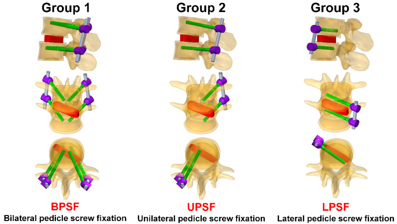
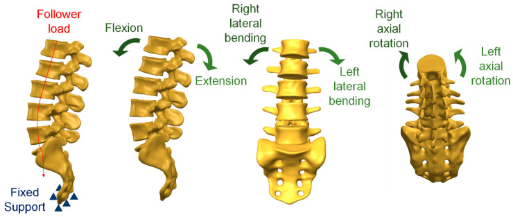
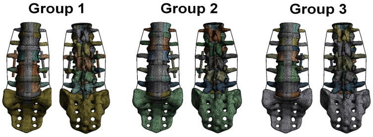
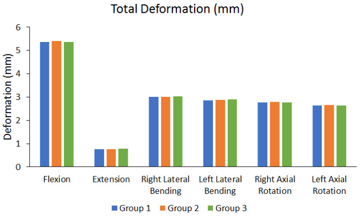
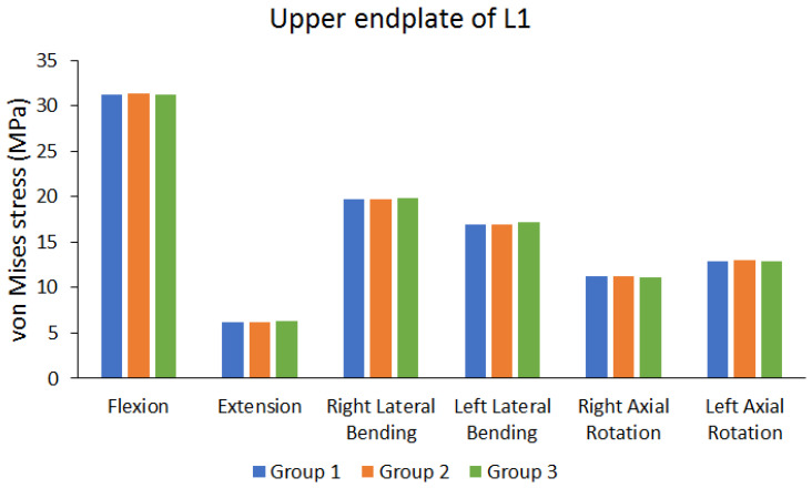
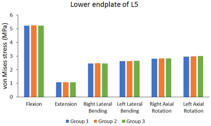
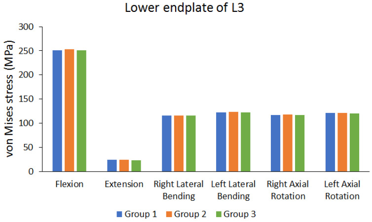
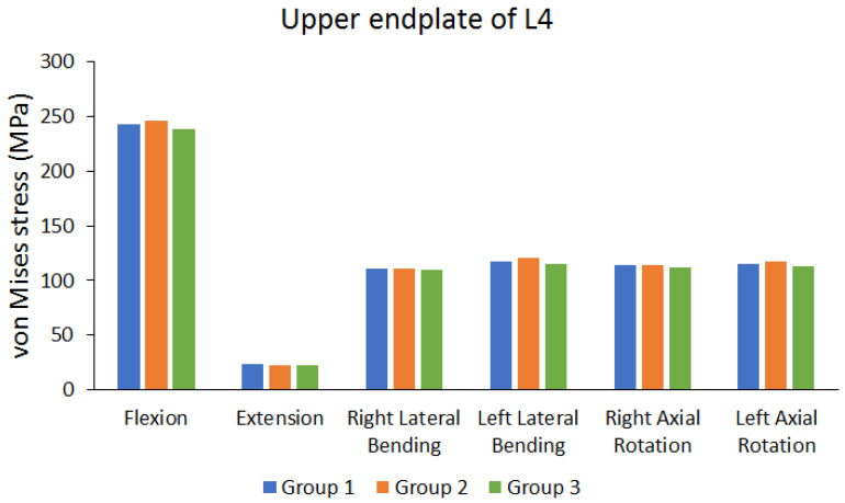
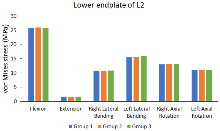
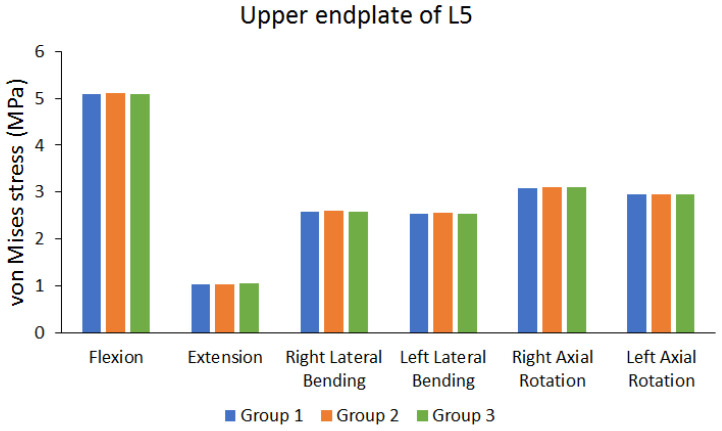
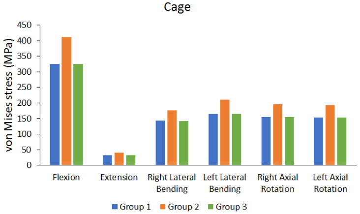
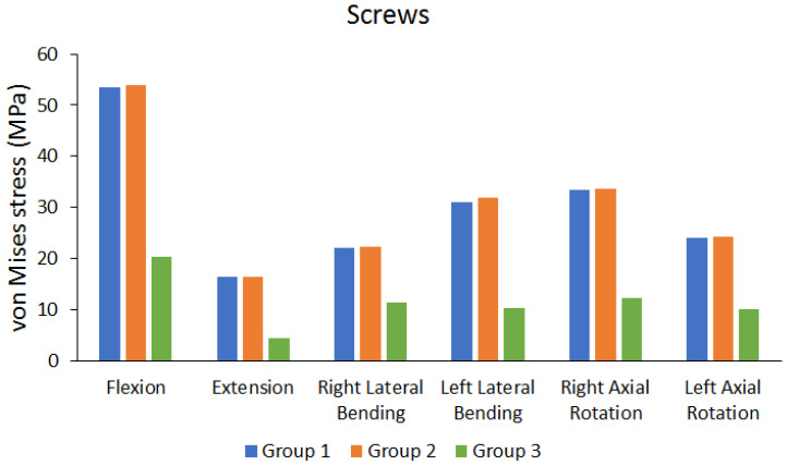
Oblique lumbar interbody fusion (OLIF) can be combined with different screw instrumentations. The standard screw instrumentation is bilateral pedicle screw fixation (BPSF). However, the operation is time consuming because a lateral recumbent position must be adopted for OLIF during surgery before a prone position is adopted for BPSF. This study aimed to employ a finite element analysis to investigate the biomechanical effects of OLIF combined with BPSF, unilateral pedicle screw fixation (UPSF), or lateral pedicle screw fixation (LPSF). In this study, three lumbar vertebra finite element models for OLIF surgery with three different fixation methods were developed. The finite element models were assigned six loading conditions (flexion, extension, right lateral bending, left lateral bending, right axial rotation, and left axial rotation), and the total deformation and von Mises stress distribution of the finite element models were observed. The study results showed unremarkable differences in total deformation among different groups (the maximum difference range is approximately 0.6248% to 1.3227%), and that flexion has larger total deformation (5.3604 mm to 5.4011 mm). The groups exhibited different endplate stress because of different movements, but these differences were not large (the maximum difference range between each group is approximately 0.455% to 5.0102%). Using UPSF fixation may lead to higher cage stress (411.08 MPa); however, the stress produced on the endplate was comparable to that in the other two groups. Therefore, the length of surgery can be shortened when unilateral back screws are used for UPSF. In addition, the total deformation and endplate stress of UPSF did not differ much from that of BPSF. Hence, combining OLIF with UPSF can save time and enhance stability, which is comparable to a standard BPSF surgery; thus, this method can be considered by spine surgeons.
Keywords: OLIF; bilateral pedicle screw fixation; biomechanics; finite element analysis; lateral pedicle screw fixation; unilateral pedicle screw fixation.
Conflict of interest statement
The authors declare no conflict of interest.
Figures
References
LinkOut - more resources
Full Text Sources
