. 2023 Nov 10;15(11):2612.
doi: 10.3390/pharmaceutics15112612.

Field-Induced Agglomerations of Polyethylene-Glycol-Functionalized Nanoclusters: Rheological Behaviour and Optical Microscopy

Affiliations

Field-Induced Agglomerations of Polyethylene-Glycol-Functionalized Nanoclusters: Rheological Behaviour and Optical Microscopy

Sandor I Bernad et al. Pharmaceutics. .

Abstract

This research aims to investigate the agglomeration processes of magnetoresponsive functionalized nanocluster suspensions in a magnetic field, as well as how these structures impact the behaviour of these suspensions in biomedical applications. The synthesis, shape, colloidal stability, and magnetic characteristics of PEG-functionalized nanoclusters are described in this paper. Experiments using TEM, XPS, dynamic light scattering (DLS), VSM, and optical microscopy were performed to study chain-like agglomeration production and its influence on colloidal behaviour in physiologically relevant suspensions. The applied magnetic field aligns the magnetic moments of the nanoclusters. It provides an attraction between neighbouring particles, resulting in the formation of chains, linear aggregates, or agglomerates of clusters aligned along the applied field direction. Optical microscopy has been used to observe the creation of these aligned linear formations. The design of chain-like structures can cause considerable changes in the characteristics of ferrofluids, ranging from rheological differences to colloidal stability changes.

Keywords: chain formation; magnetic particle targeting; magnetoresponsive nanocomposite; magnetorheological properties; optical microscopy; particle aggregation/agglomeration.


Conflict of interest statement

The authors declare no conflict of interest.

Figures

Figure 1
Figure 1
Chain-like structure development during the stent targeting processes. Magnetically induced aggregation of the PEG_MNCs in the targeted region (red arrows) at the end of the injection period of 30 s. Magnetic cluster depositions on the bottom wall of the artery model and stent struts’ coverage with magnetic clusters (yellow arrows) at the end of the injection period of 30 s. The chain-like magnetic particle structure was generated in a different part of the stent geometry in the presence of the external magnetic field. Permanent magnet positions correspond to the distance of 15 mm from the artery model bottom wall. The used magnet: rectangular NdFeB50 permanent magnet, with dimensions of 30 mm × 20 mm × 20 mm (length × width × thickness). White arrow—flow direction.
Figure 2
Figure 2
A magnetic field generated with the NbFeB52 permanent magnet was used in the experimental investigation. (A) The dimension of the used magnet and axis association. (B) A used permanent magnet has polarization along the Z-axis. (C) Numerical investigations of the magnetic field generated with the NdFeB52 magnet. (D) Bz evolution function of the magnet surface distance. Comparison between theoretical, experimental, and numerical results.
Figure 3
Figure 3
(A) Representative TEM image of the PEG-MNC clusters and aggregates. The aggregates show chain-like and close-packed morphologies (yellow arrows). (B) Detail regarding the spherical clusters (red circle) and core inside the cluster. TEM size histograms for core nanoparticles (C).
Figure 4
Figure 4
(A) Size distribution by intensity for the PEG-MNC aqueous dispersion corresponding to different time steps after the vigorous stirring of the suspension. (B) Zeta potential corresponding to the investigated PEG-MNCs’ suspension.
Figure 5
Figure 5
Particle size distribution by number obtained using DLS measurements at 60 min after manual stirring. Measurements were performed at three points corresponding to different stages of cluster sedimentation. Points P1, P2, and P3 represent the position where the samples were taken and used colloid: PEG_MNCs dispersed in distilled water.
Figure 6
Figure 6
Sedimentation curve for the 5% mass concentration PEG-MNCs dispersed in distilled water.
Figure 7
Figure 7
Particle size distribution by intensity of the 5% mass concentration PEG-MNCs dispersed in the distilled water at different time intervals after 15 min of bath sonication.
Figure 8
Figure 8
Rheological properties of the PEG_MNCs’ aqueous suspension at the temperature of 25 °C. (A) Magneto-viscous effects’ function of different magnetic flux densities for two different shear rates (0.1 and 1000 s−1); (B) viscosity curve function of time for different magnetic flux densities.
Figure 9
Figure 9
(A) Comparison between CF, aqueous, and model suspension viscosity curves at T = 25 °C. (B) CF and model suspension viscosity curves at T = 25 °C for different density values. (C,D) Viscosity curve function of time for different densities of the carrier fluid (CF) for the model suspension (CF + 5% PEG_MNC) corresponding to different magnetic flux densities.
Figure 10
Figure 10
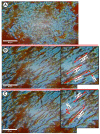
Optical microscopy investigations of the PEG-MNC aqueous suspension phase condensation phenomena induced in the presence of the external magnetic field. (A) Suspension without a magnetic field. (B) The figure shows the large PEG_MNC agglomerates generated under the action of the externally applied magnetic field of intensity H = 47 mT—detail regarding the length and thickness of these large, generated structures (chains). (C) The PEG_MNC agglomerates after turning off the magnetic field. Detail shows that the suspension contained large, micro-sized cluster agglomerates after turning off the magnetic field. All measurements of the agglomerate’s length were processed using ImageJ software—scale bar: 50 μm.
Figure 11
Figure 11
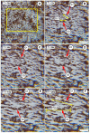
Optical microscopy images of the PEG_MNC transition from a dispersed stage to chain-like structures in the presence of the external magnetic field. (A) Suspension in the absence of the magnetic field. (BF) Stages of the chain structure’s development after the magnetic field was switched on. The investigated period is 30 s, under the action of the externally applied magnetic field of intensity H = 124 mT. (B,F) detail the length and thickness evolution during the investigated period for two agglomerates (chains), C1 and C2. (F) shows the sizeable micron-size chain structure oriented in the field direction at the end of the investigation period—scale bar: 50 μm.
Figure 12
Figure 12
Magnetic-field-induced aggregate maximum length evolution occurred during the investigated period of 30 s. The field intensity is 124 mT, corresponding to the magnet distance from the microscope plate of 7 mm. The experimental L(t) curve corresponds to chain C2 plotted in Figure 11.

Similar articles

References

    1. Douglas G., Van Kampen E., Hale A.B., McNeill E., Patel J., Crabtree M.J., Ali Z., Hoerr R.A., Alp N.J., Channon K.M. Endothelial cell repopulation after stenting determines in-stent neointima formation: Effects of bare-metal vs. drug-eluting stents and genetic endothelial cell modification. Eur. Heart J. 2012;34:3378–3388. doi: 10.1093/eurheartj/ehs240. - DOI - PMC - PubMed
    1. Fuchs A.T., Kuehnl A., Pelisek J., Rolland P.H., Mekkaoui C., Netz H., Nikol S. Inhibition of restenosis formation without compromising reendothelialization as a potential solution to thrombosis following angioplasty? Endothelium. 2008;15:85–92. doi: 10.1080/10623320802092484. - DOI - PubMed
    1. Van Belle E., Bauters C., Asahara T., Isner J.M. Endothelial regrowth after arterial injury: From vascular repair to therapeutics. Cardiovasc. Res. 1998;38:54–68. doi: 10.1016/S0008-6363(97)00326-X. - DOI - PubMed
    1. Tibbitt M.W., Dahlman J.E., Langer R. Emerging Frontiers in Drug Delivery. J. Am. Chem. Soc. 2016;138:704–717. doi: 10.1021/jacs.5b09974. - DOI - PubMed
    1. Shapiro B., Kulkarni S., Nacev A., Muro S., Stepanov P.Y., Weinberg I.N. Open challenges in magnetic drug targeting. Wiley Interdiscip. Rev. Nanomed. Nanobiotechnol. 2015;7:446–457. doi: 10.1002/wnan.1311. - DOI - PMC - PubMed

LinkOut - more resources