

Acoustic Characterization of Transmitted and Received Acoustic Properties of Air-Coupled Ultrasonic Transducers Based on Matching Layer of Organosilicon Hollow Glass Microsphere
- PMID: 38004877
- PMCID: PMC10673132
- DOI: 10.3390/mi14112021
Acoustic Characterization of Transmitted and Received Acoustic Properties of Air-Coupled Ultrasonic Transducers Based on Matching Layer of Organosilicon Hollow Glass Microsphere
Abstract
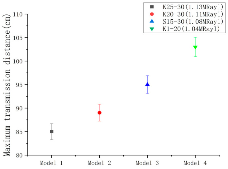
An air-coupled transducer was developed in this study, utilizing hollow glass microsphere-organosilicon composites as an acoustically matching layer, which demonstrated outstanding acoustic performance. Firstly, a comparison and analysis of the properties and advantages of different substrates was carried out to determine the potential application value of organosilicon substrates. Immediately after, the effect of hollow glass microspheres with different particle sizes and mass fractions on the acoustic properties of the matching layer was analyzed. It also evaluated the mechanical properties of the matching layer before and after optimization. The findings indicate that the optimized composite material attained a characteristic acoustic impedance of 1.04 MRayl and an acoustic attenuation of 0.43 dB/mm, displaying exceptional acoustic performance. After encapsulating the ultrasonic transducer using a 3D-printed shell, we analyzed and compared its emission and reception characteristics to the commercial transducer and found that its emission acoustic pressure amplitude and reception voltage amplitude were 34% and 26% higher, respectively. Finally, the transducer was installed onto a homemade ultrasonic flow meter for practical application verification, resulting in an accuracy rate of 97.4%.
Keywords: air-coupled transducer; composite; flowmeter; matching layer.
Conflict of interest statement
The authors declare no conflict of interest.
Figures


Similar articles
-
Fabrication and Modeling of Matching System for Air-Coupled Transducer.Micromachines (Basel). 2022 May 17;13(5):781. doi: 10.3390/mi13050781. Micromachines (Basel). 2022. PMID: 35630248 Free PMC article.
-
Determination of acoustic impedances of multi matching layers for narrowband ultrasonic airborne transducers at frequencies <2.5 MHz - Application of a genetic algorithm.Ultrasonics. 2012 Jan;52(1):169-85. doi: 10.1016/j.ultras.2011.08.001. Epub 2011 Aug 17. Ultrasonics. 2012. PMID: 21893329
-
A fiber-shaped ultrasonic transducer by designing a flexible epoxy/nano-zirconia composite as an acoustic matching layer.J Mater Chem B. 2025 Feb 26;13(9):3023-3031. doi: 10.1039/d4tb02063d. J Mater Chem B. 2025. PMID: 39887302
-
A Review of Acoustic Impedance Matching Techniques for Piezoelectric Sensors and Transducers.Sensors (Basel). 2020 Jul 21;20(14):4051. doi: 10.3390/s20144051. Sensors (Basel). 2020. PMID: 32708159 Free PMC article. Review.
-
Ultrasonic Particle Manipulation in Glass Capillaries: A Concise Review.Micromachines (Basel). 2021 Jul 26;12(8):876. doi: 10.3390/mi12080876. Micromachines (Basel). 2021. PMID: 34442498 Free PMC article. Review.
Cited by
-
Time Delay Study of Ultrasonic Gas Flowmeters Based on VMD-Hilbert Spectrum and Cross-Correlation.Sensors (Basel). 2024 Feb 23;24(5):1462. doi: 10.3390/s24051462. Sensors (Basel). 2024. PMID: 38474997 Free PMC article.
References
-
- Hu Y., Yang Y. Wave propagation modeling of the PZT sensing region for structural health monitoring. Smart Mater. Struct. 2007;16:706–716. doi: 10.1088/0964-1726/16/3/018. - DOI
-
- Liu B.T., Zhao J.W., Li X.H., Zhou Y., Bian F., Wang X.Y., Zhao Q.X., Wang Y.L., Guo Q.L., Wang L.X., et al. Enhanced dielectric constant and fatigue-resistance of PbZr0.4Ti0.6O3 capacitor with magnetic intermetallic FePt top electrode. Appl. Phys. Lett. 2010;96:252904. doi: 10.1063/1.3457382. - DOI
-
- Yu Y., Wang X., Yao X. Studies on Dynamic Mechanical and Electrical Properties of PZT Ceramics. Ferroelectrics. 2013;451:96–102. doi: 10.1080/00150193.2013.839249. - DOI
-
- Kazys R., Sliteris R., Sestoke J., Vladisauskas A. Air-Coupled Ultrasonic Transducers Based on an Application of the PMN-32%PT Single Crystals. Ferroelectrics. 2015;480:85–91. doi: 10.1080/00150193.2015.1012458. - DOI
Grants and funding
LinkOut - more resources
Full Text Sources
Miscellaneous
