Wearable Magnetic Field Sensor with Low Detection Limit and Wide Operation Range for Electronic Skin Applications
- PMID: 38037314
- PMCID: PMC11462294
- DOI: 10.1002/advs.202304525
Wearable Magnetic Field Sensor with Low Detection Limit and Wide Operation Range for Electronic Skin Applications
Abstract
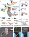
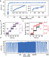
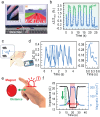
Flexible electronic devices extended abilities of humans to perceive their environment conveniently and comfortably. Among them, flexible magnetic field sensors are crucial to detect changes in the external magnetic field. State-of-the-art flexible magnetoelectronics do not exhibit low detection limit and large working range simultaneously, which limits their application potential. Herein, a flexible magnetic field sensor possessing a low detection limit of 22 nT and wide sensing range from 22 nT up to 400 mT is reported. With the detection range of seven orders of magnitude in magnetic field sensor constitutes at least one order of magnitude improvement over current flexible magnetic field sensor technologies. The sensor is designed as a cantilever beam structure accommodating a flexible permanent magnetic composite and an amorphous magnetic wire enabling sensitivity to low magnetic fields. To detect high fields, the anisotropy of the giant magnetoimpedance effect of amorphous magnetic wires to the magnetic field direction is explored. Benefiting from mechanical flexibility of sensor and its broad detection range, its application potential for smart wearables targeting geomagnetic navigation, touchless interactivity, rehabilitation appliances, and safety interfaces providing warnings of exposure to high magnetic fields are explored.
Keywords: amorphous magnetic wires; magnetic field sensor; magnetosensitive smart skins; wearable electronics; wide detection range.
© 2023 The Authors. Advanced Science published by Wiley‐VCH GmbH.
Conflict of interest statement
The authors declare no conflict of interest.
Figures


Similar articles
-
An ultrathin, rapidly fabricated, flexible giant magnetoresistive electronic skin.Microsyst Nanoeng. 2024 Aug 12;10:109. doi: 10.1038/s41378-024-00716-2. eCollection 2024. Microsyst Nanoeng. 2024. PMID: 39139649 Free PMC article.
-
Omnidirectionally Stretchable Spin-Valve Sensor Array with Stable Giant Magnetoresistance Performance.ACS Nano. 2025 Feb 11;19(5):5699-5708. doi: 10.1021/acsnano.4c15964. Epub 2025 Jan 30. ACS Nano. 2025. PMID: 39883044
-
Ultralow-Cost, Highly Sensitive, and Flexible Pressure Sensors Based on Carbon Black and Airlaid Paper for Wearable Electronics.ACS Appl Mater Interfaces. 2019 Sep 11;11(36):33370-33379. doi: 10.1021/acsami.9b12929. Epub 2019 Aug 22. ACS Appl Mater Interfaces. 2019. PMID: 31408310
-
The Progress of Research into Flexible Sensors in the Field of Smart Wearables.Sensors (Basel). 2022 Jul 6;22(14):5089. doi: 10.3390/s22145089. Sensors (Basel). 2022. PMID: 35890768 Free PMC article. Review.
-
Advances in Flexible Magnetosensitive Materials and Devices for Wearable Electronics.Adv Mater. 2024 Sep;36(37):e2311996. doi: 10.1002/adma.202311996. Epub 2024 May 29. Adv Mater. 2024. PMID: 38776537 Review.
Cited by
-
Transforming Healthcare: Intelligent Wearable Sensors Empowered by Smart Materials and Artificial Intelligence.Adv Mater. 2025 May;37(21):e2500412. doi: 10.1002/adma.202500412. Epub 2025 Apr 1. Adv Mater. 2025. PMID: 40167502 Free PMC article. Review.
References
-
- Li J., Zhao J., Rogers J. A., Acc. Chem. Res. 2019, 52, 53. - PubMed
-
- Hammock M. L., Chortos A., Tee B. C.‐K., Tok J. B.‐H., Bao Z., Adv. Mater. 2013, 25, 5997. - PubMed
-
- Huang S., Liu Y., Zhao Y., Ren Z., Guo C. F., Adv. Funct. Mater. 2019, 29, 1805924.
-
- Gao W., Ota H., Kiriya D., Takei K., Javey A., Acc. Chem. Res. 2019, 52, 523. - PubMed
Grants and funding
- U20A6001/National Natural Science Foundation of China
- M-0152/National Natural Science Foundation of China
- U1909215/National Natural Science Foundation of China
- 51931011/National Natural Science Foundation of China
- 62174165/National Natural Science Foundation of China
- 52127803/National Natural Science Foundation of China
- U22A2075/National Natural Science Foundation of China
- U22A20248/National Natural Science Foundation of China
- 51971233/National Natural Science Foundation of China
- 52201236/National Natural Science Foundation of China
- 52105286/National Natural Science Foundation of China
- 174433KYSB20200013/Chinese Academy of Sciences
- GJTD-2020-11/K.C. Wong Education Foundation
- Y2022080/Chinese Academy of Sciences Youth Innovation Promotion Association
- 2022C01032/R&D Program of Zhejiang
- 2021C01183/Zhejiang Provincial Key R&D Program
- 2022R52004/Zhejiang Provincial Key R&D Program
- LD22E010002/Natural Science Foundation of Zhejiang Province
- LGG20F010006/Zhejiang Provincial Basic Public Welfare Research Project
- 2020Z022/Ningbo Scientific and Technological Innovation 2025 Major Project
- GrantNo.2023Z097/Ningbo Key Research and Development Program
- 2022M723251/China Postdoctoral Foundation
- MA5144/13-1/German Research Foundation
- MA5144/28-1/German Research Foundation
LinkOut - more resources
Full Text Sources
Research Materials
