. 2023 Dec 2;14(1):7984.
doi: 10.1038/s41467-023-43725-x.

Sintering-induced cation displacement in protonic ceramics and way for its suppression

Affiliations

Sintering-induced cation displacement in protonic ceramics and way for its suppression

Ze Liu et al. Nat Commun. .

Abstract

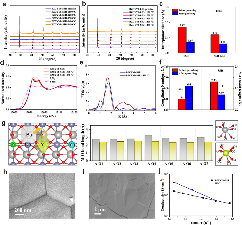
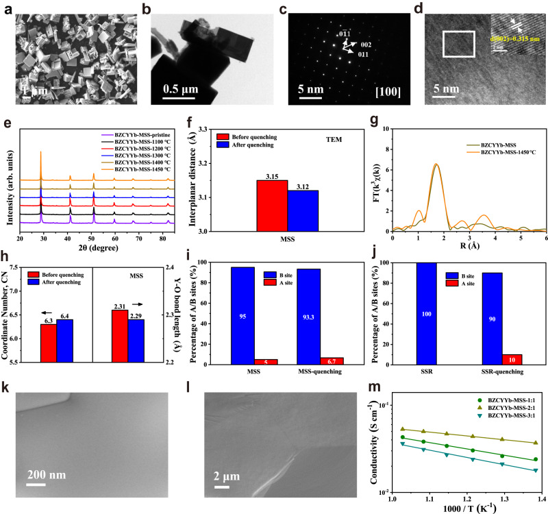
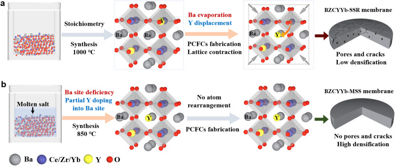
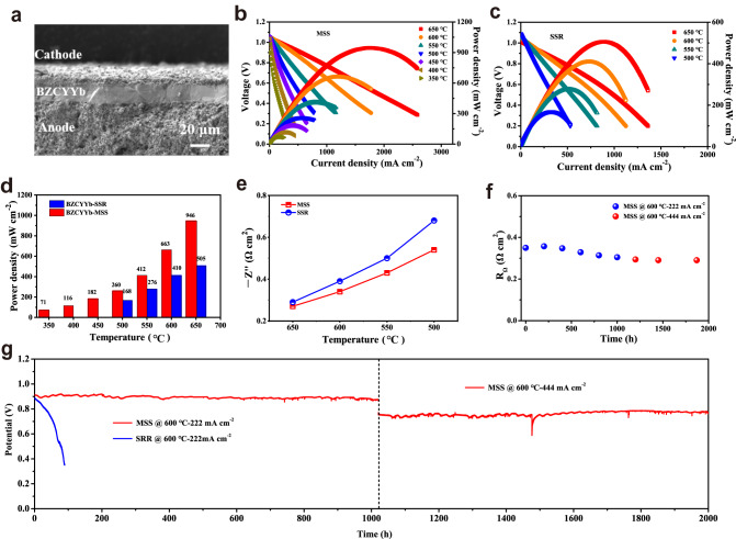
Protonic ceramic fuel cells with high efficiency and low emissions exhibit high potential as next-generation sustainable energy systems. However, the practical proton conductivity of protonic ceramic electrolytes is still not satisfied due to poor membrane sintering. Here, we show that the dynamic displacement of Y3+ adversely affects the high-temperature membrane sintering of the benchmark protonic electrolyte BaZr0.1Ce0.7Y0.1Yb0.1O3-δ, reducing its conductivity and stability. By introducing a molten salt approach, pre-doping of Y3+ into A-site is realized at reduced synthesis temperature, thus suppressing its further displacement during high-temperature sintering, consequently enhancing the membrane densification and improving the conductivity and stability. The anode-supported single cell exhibits a power density of 663 mW cm-2 at 600 °C and long-term stability for over 2000 h with negligible performance degradation. This study sheds light on protonic membrane sintering while offering an alternative strategy for protonic ceramic fuel cells development.


Conflict of interest statement

The authors declare no competing interests.

Figures

Fig. 1
Fig. 1. Study of structural evolution of BZCYYb prepared by conventional SSR method.
a, b XRD patterns of pristine BZCYYb-SSR and BZCYYb-0.93-SSR samples and after quenching at different temperatures. c The change of lattice interplanar spacing of (002) crystal plane before and after quenching at 1450 °C. d The spectra of Y K-edge XANES for BZCYYb-SSR before and after quenching at 1450 °C. e Fourier-transformed of Y K-edge EXAFS spectra of BZCYYb-SSR before and after quenching at 1450 °C. f The coordinate number and Y–O bond length for BZCYYb-SSR before and after quenching at 1450 °C. g Diagram of the Y occupying the A-site (Ba) in perovskite, and the corresponding bond length with the neighboring oxygen atoms before and after Y substitution. Surface (h) and cross-sectional (i) SEM images of BZCYYb-SSR membrane sintered at 1450 °C. j Temperature dependence of conductivity for BZCYYb-SSR and GDC membrane.
Fig. 2
Fig. 2. Structural characterizations of BZCYYb prepared by MSS method.
a SEM image of BZCYYb-MSS. b TEM image of BZCYYb-MSS. c The SAED pattern and d HR-TEM images of BZCYYb-MSS from the marked area in (b), and the insert image is a higher magnification of the marked area in (d). e XRD patterns of pristine BZCYYb-MSS and after quenching at different temperatures. f The lattice interplanar spacing of (002) crystal plane before and after quenching at 1450 °C. g Fourier-transformed of Y K-edge EXAFS spectra of BZCYYb-MSS before and after quenching at 1450 °C. h The coordinate number and Y–O bond length for BZCYYb-SSR before and after quenching at 1450 °C. i, j Proportion of Y in sites A and B of BZCYYb-MSS and BZCYYb-SSR samples before and after quenching at 1450 °C. Surface (k) and cross-sectional (l) SEM images of BZCYYb-MSS membrane sintered at 1450 °C. m Temperature dependence of conductivity for BZCYYb-MSS membrane.
Fig. 3
Fig. 3. Schematic diagrams of structural evolution.
a Schematic diagram of preparation and structural evolution of BZCYYb-SSR. b Schematic diagram of preparation of BZCYYb-MSS and inhibition of Y3+ displacement.
Fig. 4
Fig. 4. Electrochemical performances of PCFC with BZCYYb electrolyte.
a Cross-sectional SEM image of BZCYYb-MSS-based single cell after 2000 h long-term stability test. b, c I–V–P curves of BZCYYb-MSS and BZCYYb-SSR based single cell. d The comparison of the peak power densities of PCFCs with the two electrolytes. e The comparison of the ohmic resistance of the two electrolytes. f Long-term stability test of the two single cells at different constant current densities of 0.222 and 0.444 A cm−2 at 600 °C. g Time dependence of ohmic resistances of the BZCYYb-MSS-based single cell at 600 °C.

References

    1. Ding H, et al. Self-sustainable protonic ceramic electrochemical cells using a triple conducting electrode for hydrogen and power production. Nat. Commun. 2020;11:1907. doi: 10.1038/s41467-020-15677-z. - DOI - PMC - PubMed
    1. Duan C, et al. Highly efficient reversible protonic ceramic electrochemical cells for power generation and fuel production. Nat. Energy. 2019;4:230–240. doi: 10.1038/s41560-019-0333-2. - DOI
    1. Bian W, et al. Revitalizing interface in protonic ceramic cells by acid etch. Nature. 2022;604:479–485. doi: 10.1038/s41586-022-04457-y. - DOI - PubMed
    1. Duan C, et al. Readily processed protonic ceramic fuel cells with high performance at low temperatures. Science. 2015;349:1321–1326. doi: 10.1126/science.aab3987. - DOI - PubMed
    1. Pei K, et al. Surface restructuring of a perovskite-type air electrode for reversible protonic ceramic electrochemical cells. Nat. Commun. 2022;13:2207. doi: 10.1038/s41467-022-29866-5. - DOI - PMC - PubMed