. 2023 Dec 15;417(Pt B):116312.
doi: 10.1016/j.cma.2023.116312. Epub 2023 Aug 9.

A Fluid-Solid-Growth Solver for Cardiovascular Modeling

Affiliations

A Fluid-Solid-Growth Solver for Cardiovascular Modeling

Erica L Schwarz et al. Comput Methods Appl Mech Eng. .

Abstract

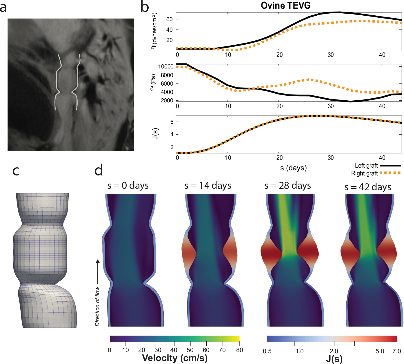
We implement full, three-dimensional constrained mixture theory for vascular growth and remodeling into a finite element fluid-structure interaction (FSI) solver. The resulting "fluid-solid-growth" (FSG) solver allows long term, patient-specific predictions of changing hemodynamics, vessel wall morphology, tissue composition, and material properties. This extension from short term (FSI) to long term (FSG) simulations increases clinical relevance by enabling mechanobioloigcally-dependent studies of disease progression in complex domains.


Conflict of interest statement

Declaration of interests The authors declare that they have no known competing financial interests or personal relationships that could have appeared to influence the work reported in this paper.

Figures

Figure 1:
Figure 1:
Schematic view of the FSG framework where timestep updates are determined by iterative convergence of the fluid-structure-growth equations. The initial in-vivo geometry pressurized under physiological conditions is chosen as the reference configuration for calculation of G&R deformations of the mixture via F(τ). The deformation experienced, at time s, by the material element of constituent α deposited at time τ is given by the deposition prestretch and subsequent deformation of the mixture expressed as Fn(τ)α(s)=F(s)F1(τ)FGα(τ) where F(s)F1(τ) represents the constrained deformation due to the deformation of the mixture and FGα(τ) represents the deposition deformation gradient (which includes the deposition prestretch). At each timestep, we enforce convergence of the governing equations of the fluid, solid, and growth domains. To do this, we iteratively update the interfacing variables of each domain. This includes the fluid velocity, un, wall shear stress, τfn, and pressure, pn(s), from the fluid domain, the solid displacement, dn, deformation gradient, Fn(s), and the intramural Cauchy stress, σfn from the solid domain, and the deformation-dependent spatial elasticity tensor, c¯(s), and deformation-dependent Cauchy stress, σ¯(s), from the growth domain. Note that there is no direct coupling from the growth domain to the fluid domain. Instead, convergence between the fluid and growth domains is indirectly mediated by the solid domain. The exact coupling algorithms and how these interfacing variables are utilized are described below.
Figure 2:
Figure 2:
Initial (a) cylindrical geometry of an ovine IVC. Increased pressure and flow (b) simulations were compared to results using a reduced-order constrained mixture model (c). The finite element results are shown by the black, solid line while the reduced-order results are shown by the purple, dotted line.
Figure 3:
Figure 3:
Impact of fluid field on outcomes are shown by simulation of an interpositional TEVG (a) with both reduced order hemodynamics (b, left) and full fluid field computation (b, right).
Figure 4:
Figure 4:
Inclusion of a fully 3D fluid field in a ovine TEVG simulation results in markedly divergent remodeling both proximally (a) and distally to the central stenosis (b).
Figure 5:
Figure 5:
Difference between mechano-mediated collagen distribution within the TEVG (a) and the thickness of native vasculature attached to the TEVG (b).
Figure 6:
Figure 6:
We segment a subject specific geometry from clinical imaging (a) and create a finite element model (b). We simulate growth and remodeling for 6 weeks (c,d) and demonstrate that the subject-specific geometry mediates growth and remodeling results (c,d).
Figure 7:
Figure 7:
Frontal cut-plane view of TEVG model showing distribution of mechano-mediated collagen (a) and axial cut-plane view of the mid-TEVG thickness in a patient-specific TEVG.
Figure 8:
Figure 8:
Aorta model generated from patient-specific imaging (a) under normal (b, left) and hypertensive (b, right) conditions.
Figure 9:
Figure 9:
In patient-specific aortas, there are significant differences in the time-resolved remodeling of the outer (a) and inner (b) aortic arch that are both geometry and pathology-dependent.
Figure 10:
Figure 10:
Distribution of collagen (a) and thickness (b) in a normal and hypertensive aorta model.
Figure 11:
Figure 11:
Aortic simulations under pulsatile inflow (a). The differential remodeling under normal (b) and hypertensive (c) results in distinct responses over the cardiac cycle. Pulsatile displacement is calculated respect to the diastolic configuration.

References

    1. Rodriguez EK, Hoger A, and McCulloch AD, “Stress-dependent finite growth in soft elastic tissues,” Journal of biomechanics, vol. 27, no. 4, pp. 455–467, 1994. - PubMed
    1. Fung Y, Liu S, and Zhou J, “Remodeling of the constitutive equation while a blood vessel remodels itself under stress,” Journal of Biomechanical Engineering, 1993. - PubMed
    1. Menzel A and Kuhl E, “Frontiers in growth and remodeling,” Mechanics research communications, vol. 42, pp. 1–14, 2012. - PMC - PubMed
    1. Humphrey J, “Constrained mixture models of soft tissue growth and remodeling–twenty years after,” Journal of Elasticity, vol. 145, no. 1, pp. 49–75, 2021. - PMC - PubMed
    1. Irons L and Humphrey JD, “Cell signaling model for arterial mechanobiology,” PLoS computational biology, vol. 16, no. 8, p. e1008161, 2020. - PMC - PubMed

LinkOut - more resources