. 2023 Dec 15;9(50):eadj0883.
doi: 10.1126/sciadv.adj0883. Epub 2023 Dec 15.

Modularized microrobot with lock-and-detachable modules for targeted cell delivery in bile duct

Affiliations

Modularized microrobot with lock-and-detachable modules for targeted cell delivery in bile duct

Lin Su et al. Sci Adv. .

Abstract

The magnetic microrobots promise benefits in minimally invasive cell-based therapy. However, they generally suffer from an inevitable compromise between their magnetic responsiveness and biomedical functions. Herein, we report a modularized microrobot consisting of magnetic actuation (MA) and cell scaffold (CS) modules. The MA module with strong magnetism and pH-responsive deformability and the CS module with cell loading-release capabilities were fabricated by three-dimensional printing technique. Subsequently, assembly of modules was performed by designing a shaft-hole structure and customizing their relative dimensions, which enabled magnetic navigation in complex environments, while not deteriorating the cellular functionalities. On-demand disassembly at targeted lesion was then realized to facilitate CS module delivery and retrieval of the MA module. Furthermore, the feasibility of proposed system was validated in an in vivo rabbit bile duct. Therefore, this work presents a modular design-based strategy that enables uncompromised fabrication of multifunctional microrobots and stimulates their development for future cell-based therapy.


Figures

Fig. 1.
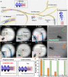
Fig. 1.. Schematic of the modularized microrobot system for targeted cell delivery in BD.
The system was prepared by assembling a CS module and an MA module, whose assembled state was locked and unlocked by the pH-responsive volume expansion and contraction of MA module, respectively. During the cell delivery process, the modularized microrobot was deployed by catheter to the vicinity of the lesion site and then navigated to the targeted region under the actuation of a rotating magnetic field with a high frequency (RMF fhigh, stage 1), at which a corkscrew motion occurred. Once arriving at the lesion site with acidic environment, on-demand disassembly was performed by the combined application of a rotating magnetic field with a low frequency (RMF flow), contributing to the detachment of CS module for therapeutic purposes (stage 2). At relatively low frequency, the microrobot wobbled about its helix axis. At stage 3, the individual MA module was retrieved by catheter under the actuation of a rotating magnetic field to minimize the potential biosafety risk.
Fig. 2.
Fig. 2.. 3D printing and characterization of specialized modules.
(A) Schematic of the 3D printing process of MA and CS modules. (B) The developed pH-responsive magnetic hydrogel precursor and biodegradable hydrogel precursor for MA and CS modules, respectively. (C) SEM images of the printed MA module. (D) Magnetic hysteresis loop of pH-responsive magnetic hydrogel doped with 33–wt % NdFeB particles. (E) The diameter variation of the MA module axial rod with the change of pH value between 7.0 and 5.0. Scale bar, 800 μm. Error bars represented the SD (n = 3). (F) SEM image of the printed CS module. (G) The viability of stem cells after incubation with different biodegradable hydrogels. Error bars represented the SD (n = 3). (H) The effect of collagenase-2 enzyme concentration on the degrading time of biodegradable hydrogel (GelMA4-AAm8). Error bars represent the SD (n = 3). (I) Optical images of CS module enzymatic degradation process. (J) Fluorescence images of MSCs loaded on CS module. (K) Fluorescence and optical images of the MSCs releasement from CS module after enzymatic treatment.
Fig. 3.
Fig. 3.. Robust assembly and controllable disassembly of modularized microrobot from specialized modules.
(A) Schematic and representative images of the assembly and disassembly process. (i) In the pristine state, MA module was contracted by adding acidic buffer to facilitate the penetration into CS module. (ii) Changing the environmental pH to neutral made MA module swell in situ, contributing to locking the assembly state of modularized microrobot. (iii) Under the combined application of acidic stimulus and a rotating magnetic field with a low frequency (RMF flow), MA module shrank and wobbled, leading to the disassembly of microrobot (iv). Scale bar, 800 μm. (B) The phase diagram showing the assembled state of modularized microrobot with various interference fit (i) under different motion modes. The illustrations showed the representative experimental results. (C) The propulsion velocity as a function of rotation frequency. The viscosity of environment is 1 cP. Error bars represent the SD (n = 3). (D) The effect of environmental pH on the disassembled time of microrobot. Error bars represent the SD (n = 3). (E) The effect of magnetic field rotating frequency on the disassembled time and wobbling angle of the microrobot. Error bars represent the SD (n = 5). The maximum strength of magnetic field Bmag is 27 mT. (F) The effect of fluid viscosity on the disassembled time and wobbling angle of the microrobot. Error bars represented the SD (n = 5). (Bmag = 27 mT)
Fig. 4.
Fig. 4.. In vitro demonstration of magnetic navigation, on-demand disassembly and retrieval of the microrobot in a 3D-printed model of BD.
(A) Schematics of the magnetic steering of the modularized microrobot in simulated BD. The blue zone represents the targeted site with an acidic environment. (B) Representative experimental images of the modularized microrobot in BD model, including the deployment at the vicinity of targeted site by catheter (i), controllable navigation across bifurcations to reach the target (ii and iii), on-demand disassembly at lesion (iv), and retrieval of MA module (v and vi). (C) Schematic comparison between the microrobot with and without interacted modules. (D) Experimental results of two microrobot designs during their navigation across a bifurcation in BD model, indicating the indispensable role of effective assembly. (E) The access rate of CS module at the deployment location and the following three bifurcations for two microrobot designs, indicating a higher targeting efficiency of our modularized system. The number of trials was 3. (Bmag = 27 mT, fmag = 13 Hz)
Fig. 5.
Fig. 5.. Ex vivo demonstration of the magnetic locomotion and disassembly of the modularized microrobot in porcine BD under the guidance of medical imaging modalities.
(A) Schematic of medical imaging-guided delivery of modularized microrobot inside BD tissue. The platform included a catheter, a magnetic control system (a rotating permanent magnet integrated on a six-axis robotic arm), and two imaging systems (C-arm fluoroscopy and US imaging). (B) Experimental setup for x-ray fluoroscopy-guided navigation of modularized microrobot in the porcine BD. (C) Representative x-ray images of the magnetic navigation process in the BD. The modularized microrobot was deployed via a catheter (i) and magnetically steered across bifurcation to the termination of desired branch (ii and iii). In addition, it could move back (iv) and be retrieved via a catheter (v) under the actuation of an external magnetic field. The working distance between the magnet and BD ranged from 20 cm. (D) Experimental setup for US imaging–guided disassembly of the modularized microrobot in the porcine BD. (E) Representative US images of the on-demand disassembly process in BD. When the modularized microrobot arrived at the targeted region with acidic environment (i), MA module contracted (ii) and wobbled to initiate the disassembly at lesion sites (iii). Dashed blue curves marked the targeted area, and the modularized microrobot was highlighted by dashed red curves.
Fig. 6.
Fig. 6.. In vivo targeted delivery of modularized microrobot in a rabbit BD under the guidance of x-ray imaging.
(A) Schematic illustration showing the in vivo delivery of modularized microrobot to target rabbit BD. The schematic of rabbit BD is referred to (73, 74) (B) Experimental setup for the fluoroscopic imaging-guided navigation of modularized microrobot in the rabbit BD. The rabbit was fixed to a dissecting bench. The experimental platform included a magnetic control system (a rotating permanent magnet integrated into a six-axis robotic arm), anesthetic equipment, and an imaging system (C-arm fluoroscopy). (C) The x-ray image of the rabbit BD. (D) The representative fluoroscopic images of navigation and delivery of modularized microrobot in the rabbit BD. The modularized microrobot was deployed via a catheter and magnetically steered to access the termination of the desired branch (i to iii). When the modularized microrobot arrived at the targeted region with an acidic environment, the modules were disassembled, and the separated MA module was driven to move back to the initial position for retrieval (iv to vi). The modularized microrobot was highlighted by dashed red curves. The working distance was larger than 10 cm. Parts of this figure were created with Biorender.com.

References

    1. G. Q. Daley, D. T. Scadden, Prospects for stem cell-based therapy. Cell 132, 544–548 (2008). - PubMed
    1. J. M. Hallett, S. Ferreira-Gonzalez, T. Y. Man, A. M. Kilpatrick, H. Esser, K. Thirlwell, M. T. Macmillan, D. Rodrigo-Torres, B. J. Dwyer, V. L. Gadd, C. Ashmore-Harris, W.-Y. Lu, J. P. Thomson, M. A. Jansen, E. O’Duibhir, P. J. Starkey Lewis, L. Campana, R. E. Aird, T. S. R. Bate, A. R. Fraser, J. D. M. Campbell, G. C. Oniscu, D. C. Hay, A. Callanan, S. J. Forbes, Human biliary epithelial cells from discarded donor livers rescue bile duct structure and function in a mouse model of biliary disease. Cell Stem Cell 29, 355–371.e10 (2022). - PMC - PubMed
    1. C. J. Bashor, I. B. Hilton, H. Bandukwala, D. M. Smith, O. Veiseh, Engineering the next generation of cell-based therapeutics. Nat. Rev. Drug Discov. 21, 655–675 (2022). - PMC - PubMed
    1. T. J. Kean, P. Lin, A. I. Caplan, J. E. Dennis, MSCs: Delivery routes and engraftment, cell-targeting strategies, and immune modulation. Stem Cells Int. 2013, 732742 (2013). - PMC - PubMed
    1. T. Zhou, Z. Yuan, J. Weng, D. Pei, X. Du, C. He, P. Lai, Challenges and advances in clinical applications of mesenchymal stromal cells. J. Hematol. Oncol. 14, 24 (2021). - PMC - PubMed

Publication types