. 2023 Dec 16;14(1):8385.
doi: 10.1038/s41467-023-44273-0.

UV-curable thiol-ene system for broadband infrared transparent objects

Affiliations

UV-curable thiol-ene system for broadband infrared transparent objects

Piaoran Ye et al. Nat Commun. .

Abstract

Conventional infrared transparent materials, including inorganic ceramic, glass, and sulfur-rich organic materials, are usually processed through thermal or mechanical progress. Here, we report a photo-curable liquid material based on a specially designed thiol-ene strategy, where the multithiols and divinyl oligomers were designed to contain only C, H, and S atoms. This approach ensures transparency in a wide range spectrum from visible light to mid-wave infrared (MWIR), and to long-wave infrared (LWIR). The refractive index, thermal properties, and mechanical properties of samples prepared by this thiol-ene resin were characterized. Objects transparent to LWIR and MWIR were fabricated by molding and two-photon 3D printing techniques. We demonstrated the potential of our material in a range of applications, including the fabrication of IR optics with high imaging resolution and the construction of micro-reactors for temperature monitoring. This UV-curable thiol-ene system provides a fast and convenient alternative for the fabrication of thin IR transparent objects.


Conflict of interest statement

The authors declare no competing interests.

Figures

Fig. 1
Fig. 1. Molecular structures of multithiol-divinyl oligomer (DVO) system and the long-wave infrared (LWIR) transmission results for pre-screening.
a Scheme of monomer and resin preparation for the study; (b) proposed di-vinyl oligomers(DVO) that will be selected; (c) model compounds that used in computation. d Experimental LWIR transmission percentage of samples (500 μm thickness) prepared using DVO(2-10) and polySH; (e) simulated LWIR intensity of compounds in (c). The yellow regions refer to potential windows transparent to LWIR. Source data are provided as a Source Data file.
Fig. 2
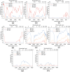
Fig. 2. Broad band IR transmission results of samples with different thickness.
Long-wave infrared (LWIR) transmission of samples prepared using (a) TetraSH with divinyl oligomer (DVO2), (b) polySH with DVO2, (c) diurethane dimethacrylate (DUDMA), and (d) pentaerythritol tetraacrylate (PETA) with different thicknesses. Mid-wave infrared (MWIR) transmission of samples prepared using (e) tetraSH with DVO2, (f) polySH with DVO2, (g) DUDMA, and (h) PETA. Source data are provided as a Source Data file.
Fig. 3
Fig. 3. Thermal and mechanical properties of cured tetraSH-divinyl oligomer (DVO2) and polySH-DVO2.
a Differential scanning calorimetry (DSC) and (b) dynamic mechanical analysis (DMA) of samples after thermally post-curing treatment; (c) stress-strain curve of samples prepared with tetraSH and DVO2; (d) stress-strain curve of samples prepared with polySH and DVO2; (e) comparison of samples’ ultimate stress before and after thermally post-curing. Error bars: Standard Error; (f) comparison of samples’ ultimate strain before and after thermally post-curing. Error bars: Standard Error; (g) cyclic tensile testing of samples prepared with tetraSH and DVO2; (h) cyclic tensile testing of samples prepared with polySH and DVO2. Source data are provided as a Source Data file.
Fig. 4
Fig. 4. Mid-wave infrared (MWIR) imaging performance of lenses fabricated by molding or 3D printing.
Sc heme of set up for MWIR imaging experiments with (a) transmission strategy and set up for imaging experiments of USAF 1951 target with reflection strategy. be Imaging taken with commercial lens, lens molded with tetraSH and divinyl oligomer (DVO2) resin, lens molded with polySH and DVO2 resin, and lens molded with PETA, respectively. All the molded lenses have a diameter of 6 mm and a thickness of 180 µm. f Image of human face obtained with MWIR sensor and a commercial lens. g Image of human face obtained with MWIR sensor and molded lens. h The reflection imaging result of a USAF 1951 target as a reflective target. The main body of the USAF target is made of glass and the numbers and marks on this target are coated with chrome with high reflectivity of IR light. The middle image in the dashed green box is a magnification of the region in the dashed green box in the left image. The inset contrast intensity profile (right panel) refers to three elements covered by the yellow dashed line on the middle image. i Scheme of fabrication of lens array for the experiment. A 3 × 3 lens array was printed on a NaCl plate by two-photon polymerization using resin prepared with tetraSH and DVO2. A polymer mask containing 3X3 holes fitting to the lens array was 3D printed by a commercial digital light processing (DLP) printer and commercial resin to block light that does not pass through the lens array. Scale bar: 1 mm. j Scheme of the imaging system for experiments. The printed lens array and molded lens were assembled in a frame to maximize the imaging quality. The setup with black tape mask was shown in Supplementary Fig. 17. Both the transmission strategy (top) and reflection strategy (bottom) were employed during the experiments. k Imaging results obtained using transmission strategy of steel masks with single hole (left, 5 mm diameter), vertical grille (middle, 2 mm width), and mesh grille (right, 2 ×2 mm for every single lattice). l Imaging results obtained using reflection strategy of USAF target (left and middle) and a steel ruler (right) as reflection targets.
Fig. 5
Fig. 5. Long-wave infrared (LWIR) imaging performance of lenses fabricated by molding.
a Scheme of assembling LWIR camera using the molded lens. The assembled camera can connect to a cellphone to capture images or record video using an APP provided by Seek Thermal. b LWIR imaging result of a mesh grille using lens molded using tetraSH and divinyl oligomer (DVO2). c LWIR imaging result of a mesh grille using lens molded using pentaerythritol tetraacrylate (PETA). d LWIR imaging result of a tree under sun exposure using lens molded by polySH and DVO2. The left picture is a visible light picture taken by a cellphone. The slight difference between visible and IR pictures was due to the small difference in field of view and the photographing angles between the cellphone and the assembled IR camera. e Scheme of adjusting imaging distance for LWIR imaging using the 3D printed mounting structure. fh The field of view (FOV) and magnification change as the imaging distance increases. The imaging experiments were conducted with the reflection strategy. Panel (g) refers to the region in the dashed green box in Panel (f). The middle image in Panel (h) refers to the region covered by the dashed yellow line in the image to its left. The inset contrast intensity profile (Panel h, right) refers to the three elements covered by this dashed yellow line.
Fig. 6
Fig. 6. Performance of 3D printed micro-reactor for temperature monitoring.
a Scheme of using an Long-wave infrared (LWIR) camera to monitor temperature change inside of a printed micro-reactor. The IR transparent wall faced the camera. The wall thickness is 100 µm. b The 5 M NaOH was mixed with DI water. The temperature change is not significant enough to be detected with the set up. c The 5 M NaOH was mixed with 5 M HCl. The reactor turned brighter in the LWIR range right away after the NaOH was added. d A NaOH particle was added to the 5 M HCl. The reactor became much brighter in LWIR range. e The IR untransparent wall faced the camera. The wall thickness is 100 µm. f The temperature change inside the reactor cannot be detected when the diurethane dimethacrylate (DUDMA) wall faced the camera.
Fig. 7
Fig. 7. Steps of synthesizing multithiols.
a Synthesis of 1-chloro-3-(hydroxyethylthio)-2-propanol (CHTEP). b Synthesis of tetraol. c Synthesis of tetrathiol. d Synthesis of polythiol.

References

    1. Bellisola G, Sorio C. Infrared spectroscopy and microscopy in cancer research and diagnosis. Am. J. Cancer Res. 2012;2:1–21. - PMC - PubMed
    1. Badakis, G., Koutsoubelias, M. & Lalis, S. In 2021 IEEE Sensors Applications Symposium (SAS). 1-6. 10.1109/SAS51076.2021.9530091.
    1. Hussain R, Zeadally S. Autonomous cars: Research results, issues, and future challenges. IEEE Commun. Surv. Tutor. 2019;21:1275–1313. doi: 10.1109/COMST.2018.2869360. - DOI
    1. Coffey VC. Seeing in the dark: Defense applications of IR imaging. Opt. Photon. N. 2011;22:26–31. doi: 10.1364/OPN.22.4.000026. - DOI
    1. Rieke GH, et al. The mid-infrared instrument for the james webb space telescope, i: Introduction. Publ. Astronomical Soc. Pac. 2015;127:584. doi: 10.1086/682252. - DOI