. 2024 Mar;11(9):e2306032.
doi: 10.1002/advs.202306032. Epub 2023 Dec 18.

Rotaxane-Functionalized Dyes for Charge-Rectification in p-Type Photoelectrochemical Devices

Affiliations

Rotaxane-Functionalized Dyes for Charge-Rectification in p-Type Photoelectrochemical Devices

Tessel Bouwens et al. Adv Sci (Weinh). 2024 Mar.

Abstract

A supramolecular photovoltaic strategy is applied to enhance power conversion efficiencies (PCE) of photoelectrochemical devices by suppressing electron-hole recombination after photoinduced electron transfer (PET). Here, the author exploit supramolecular localization of the redox mediator-in close proximity to the dye-through a rotaxane topology, reducing electron-hole recombination in p-type dye-sensitized solar cells (p-DSSCs). Dye PRotaxane features 1,5-dioxynaphthalene recognition sites (DNP-arms) with a mechanically-interlocked macrocyclic redox mediator naphthalene diimide macrocycle (3-NDI-ring), stoppering synthetically via click chemistry. The control molecule PStopper has stoppered DNP-arms, preventing rotaxane formation with the 3-NDI-ring. Transient absorption and time-resolved fluorescence spectroscopy studies show ultrafast (211 ± 7 fs and 2.92 ± 0.05 ps) PET from the dye-moiety of PRotaxane to its mechanically interlocked 3-NDI-ring-acceptor, slowing down the electron-hole recombination on NiO surfaces compared to the analogue . p-DSSCs employing PRotaxane (PCE = 0.07%) demonstrate a 30% PCE increase compared to PStopper (PCE = 0.05%) devices, combining enhancements in both open-circuit voltages (VOC = 0.43 vs 0.36 V) and short-circuit photocurrent density (JSC = -0.39 vs -0.34 mA cm-2 ). Electrochemical impedance spectroscopy shows that PRotaxane devices exhibit hole lifetimes (τh ) approaching 1 s, a 16-fold improvement compared to traditional I- /I3 - -based systems (τh = 50 ms), demonstrating the benefits obtained upon nanoengineering of interfacial dye-regeneration at the photocathode.

Keywords: femtosecond transient absorption; interfacial photoelectrochemistry; p-type dye-sensitized solar cell; rotaxanes; supramolecular electronics.


Conflict of interest statement

The authors declare no conflict of interest.

Figures
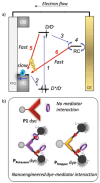
Figure 1
Figure 1
a) Schematic representation of forward electron propagation steps (1–4) (blue arrows) and recombination pathways (5, 6) (red arrows) leading to efficiency losses within p‐DSSCs. FTO = fluorine‐doped tin oxide; band; CB = conduction band; D = dye; RC = redox couple. a) Schematic representation of the benchmark system P1 dye (no mediator interaction) and PRotaxane/PStopper dyes comprising nanoengineered dye‐mediator interactions. PRotaxane contains a permanently bound mediator as a built‐in regeneration system and PStopper is designed as a control to study the influence of a permanently bound mediator. The 3‐NDI‐ring is represented as a purple ring in the figure.
Figure 2
Figure 2
Molecular structures of the benchmark dye P1, the macrocyclic redox mediator 3‐NDI‐ring, Protaxane, and PStopper.
Figure 3
Figure 3
UV–vis spectra in MeCN of PRotaxane (solid violet line), PStopper (solid orange line), and compound 3‐NDI‐ring (red solid line) along with the normalized fluorescence spectrum upon excitation at λ max (PRotaxane: violet dashed line, PStopper: orange dashed line, 3‐NDI‐ring: red dashed line). Fluorescence spectra are normalized with respect to the fluorescence intensity of PStopper at 295 nm.
Figure 4
Figure 4
Cyclic voltammograms (0.1 M TBAPF6 in DCM, 0.1 V s−1) of PStopper (orange line), PRotaxane (violet solid line) (0.2 mM each), and 3‐NDI‐ring (red line) (0.5 mM). The arrow indicates the scanning direction. Note: The last reduction of 3‐NDI‐ring of PRotaxane cannot be discerned through CV but is visible through differential pulse voltammetry (DPV, Figure S23, Supporting Information).
Figure 5
Figure 5
Decay of the normalized fluorescence signal at 615 nm (λ exc. = 532 nm) and fits for both ZrO2|PStopper and ZrO2|PRotaxane. Note that the fluorescence of the latter is quenched, negatively affecting the signal‐to‐noise ratio and quality of the fit.
Figure 6
Figure 6
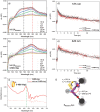
Transient absorption (TA, λ exc. = 480 nm) data and fits (see Section S2, Supporting Information for details) of PRotaxane on NiO in supporting electrolyte (1.5 mL, 1 M LiTFSI valeronitrile/MeCN, 15:85) in absence and presence of the 3‐NDI‐ring (5.9 mM). a) TA spectra at given time delays in the absence of the 3‐NDI‐ring. The photoinduced absorbance of NiO|PRotaxane around 575 nm is indicated with a black dashed line and indicative of a combination of PRotaxane * and PRotaxane ; b) TA spectra at given time delays in the presence of the 3‐NDI‐ring ; c) Spectroelectrochemistry of the 3‐NDI‐ring (dotted green line), which shows an absorption band around 608 nm when the 3‐NDI‐ring is formed (solid red line); d) Kinetic traces at 575 nm with (red) and without 3‐NDI‐ring present in the electrolyte (black); e) Kinetic traces at 620 nm with (red) and without 3‐NDI‐ring present in the electrolyte (black); f) Schematic representation of charge transfer processes following excitation of the PRotaxane dye in absence of free 3‐NDI‐ring.
Figure 7
Figure 7
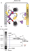
a) Schematic representation of charge propagation of the rotaxane‐based p‐DSSC. b) Schematic energy diagram for the p‐DSSC based on the PRotaxane/PStopper dyes. Upon excitation of the PRotaxane hole injection takes place (process 1a) and simultaneously the mechanically bound 3‐NDI‐ring@PRotaxane is reduced (process 1b). Then, the reduced 3‐NDI‐ring•−@PRotaxane is able to reduce the 3‐NDI‐ring present in the bulk solution (process 2). Energy levels are represented in V versus NHE.
Figure 8
Figure 8
Photovoltaic performances of the devices based on the Pstopper (orange line) and the PRotaxane dye (violet line) with the 3‐NDI‐ring as redox mediator (25 mM 3‐NDI‐ring/3‐NDI‐ring 1:1 in 1 M LiTFSI valeronitrile/MeCN, 15:85). a) JV curves of the on the Pstopper (orange line) and the PRotaxane dye (violet line). b) Photocurrent action spectrum. c) Chopped light amperometry at different light flux varying from 0.05–1.3 W cm−2 with on/off cycles of 10 s. d) Zoom of chopped light amperometry at 80, 90, and 100 mW cm−2 clearly showing tailing behavior indicative of mass transfer limitation.

References

    1. Mcgarraugh H. H., Liu W., Matthews B. P., Smith B. D., Eur. J. Org. Chem. 2019, 2019, 3489. - PMC - PubMed
    1. Ngo T. H., Labuta J., Lim G. N., Webre W. A., D'souza F., Karr P. A., Lewis J. E. M., Hill J. P., Ariga K., Goldup S. M., Chem. Sci. 2017, 8, 6679. - PMC - PubMed
    1. Arunkumar E., Fu N., Smith B. D., Chemistry 2006, 12, 4684. - PubMed
    1. Goto Y., Hisatomi T., Wang Q., Higashi T., Ishikiriyama K., Maeda T., Sakata Y., Okunaka S., Tokudome H., Katayama M., Akiyama S., Nishiyama H., Inoue Y., Takewaki T., Setoyama T., Minegishi T., Takata T., Yamada T., Domen K., Joule 2018, 2, 509.
    1. Li H., Fahrenbach A. C., Coskun A., Zhu Z., Barin G., Zhao Y.‐L., Botros Y. Y., Sauvage J.‐P., Stoddart J. F., Angew. Chem., Int. Ed. 2011, 50, 6782. - PubMed

LinkOut - more resources