. 2024 Mar;11(9):e2305950.
doi: 10.1002/advs.202305950. Epub 2023 Dec 21.

Fluid Ferroelectric Filaments

Affiliations

Fluid Ferroelectric Filaments

Marcell T Máthé et al. Adv Sci (Weinh). 2024 Mar.

Abstract

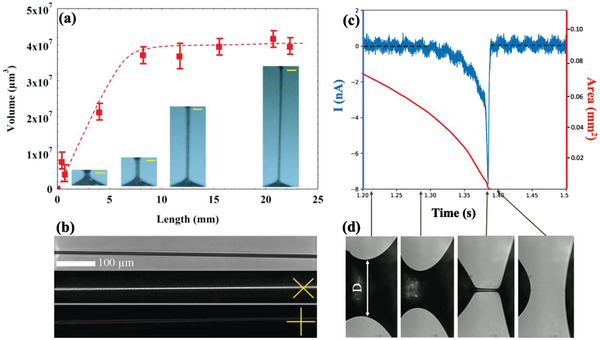
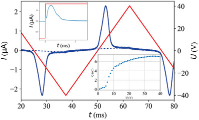
Freestanding slender fluid filaments of room-temperature ferroelectric nematic liquid crystals are described. They are stabilized either by internal electric fields of bound charges formed due to polarization splay or by external voltage applied between suspending wires. The phenomenon is similar to those observed in dielectric fluids, such as deionized water, except that in ferroelectric nematic materials the voltages required are three orders of magnitudes smaller and the aspect ratio is much higher. The observed ferroelectric fluid threads are not only unique and novel but also offer measurements of basic physical quantities, such as the ferroelectric polarization and viscosity. Ferroelectric nematic fluid threads may have practical applications in nano-fluidic micron-size logic devices, switches, and relays.

Keywords: electrically stabilized threads; ferroelectric liquid; fluid filaments.


Conflict of interest statement

The authors declare no conflict of interest.

Figures

Figure 1
Figure 1
Summary of the behavior of N Ffilaments without electric fields. a) Length dependence of the volume of a FNLC 919 freestanding filament. Insets in the bottom show the vertically aligned filaments at different lengths. Yellow bars show 100 µm length. Data presented as mean ± SD, n = 3. b) Pictures of a filament without polarizers (top); between crossed polarizers at ≈± 45° (middle) and 0,  90°(bottom) with respect to the horizontal direction. c) Time dependence of the electric current flowing through the material bridge during pulling (blue line plotted against the left axis) and the area of the waist of the bridge/ thread (red line plotted against the right axis). d) Side views of the bridges at several selected times shown by arrows between (c) and (d).
Figure 2
Figure 2
Summary of the observations on N F filaments in longitudinal DC fields. a) Maximum length L max as a function of DC voltage applied between two supporting wires (160 µm diameter). Data presented as mean ± SD, n = 3. Insets b–e) show the filament at increasing length and slenderness ratio S  =  length/diameter, while pulling in the presence of U = 20 V DC voltage. f,g) show observation in transmission of a piece of horizontal thread doped with a dichroic dye (disperse orange 3) and illuminated by blue light polarized horizontally (f) and vertically (g).
Figure 3
Figure 3
Summary of the transversal vibration of the filaments in longitudinal AC fields. a) Time dependence of the displacement of the transversal oscillation in x direction of a 3 mm long thread with the best fit after the sign of 50 Vsquare wave voltage has been switched between the suspending horizontal wires. Inset in the top shows the frequency dependence of the amplitude of the oscillation for 70 V sinusoidal voltage applied horizontally. Data presented as mean ± SD, n = 10. b) Snapshots of the filaments at different phases during the oscillation, while we applied U  =  50 V, f  =  40 Hz sinusoidal signal. c) Standing waves on the thread with different length when we applied U  =  90 V, f  =  20 Hz sinusoidal signal.
Figure 4
Figure 4
Summary of electric current measurements on axial field stabilized FNLC threads. Main pane: time dependence of the electric current flowing in a 500 µm long 400 µm diameter thread under 40 V, 20 Hz triangular wave voltage. The bottom‐right inset shows the voltage dependence of the electric charge accumulated on the wires. The top‐left inset shows the time dependence of the electric current under sign inversion of 40 V,  10 Hz square wave voltage. Data presented as mean, n = 8.
Figure 5
Figure 5
Schematic explanation of the filament stabilization and their transversal vibration in longitudinal AC electric fields. a–c) Illustration of the physical mechanism leading to FNLC filaments. a) Sessile droplets with tangential polarization field before touching each other; b) Fluid bridge with hour‐glass shape and polarization along the substrates; c) Formation of the filament with polarization along the long axis and bound charges between the ends; d) Illustration of the periodic forces leading to transversal vibrations as an effect of the longitudinal electric field.

References

    1. Rayleigh L., Proc. Lond. Math. Soc. 1880, 11, 57.
    1. Rayleigh L., J. Sci. 1892, 34, 145.
    1. de Gennes P. G., Prost J., in The Physics of Liquid Crystals, Claredon Press, Oxford: 1993.
    1. Jakli A., Saupe A., in One‐ and Two‐ Dimensional Fluids: Properties of Smectic, Lamellar and Columnar Liquid Crystals, Taylor And Francis, Boca Raton: 2006.
    1. Cheong A.‐G., Rey A. D., Mather P. T., Phys. Rev. E 2001, 64, 41701.

LinkOut - more resources