. 2023 Dec 7;14(12):2213.
doi: 10.3390/mi14122213.

A Rapid Prototyping Approach for Multi-Material, Reversibly Sealed Microfluidics

Affiliations

A Rapid Prototyping Approach for Multi-Material, Reversibly Sealed Microfluidics

Michael Halwes et al. Micromachines (Basel). .

Abstract

Microfluidic organ-on-chip models recapitulate increasingly complex physiological phenomena to study tissue development and disease mechanisms, where there is a growing interest in retrieving delicate biological structures from these devices for downstream analysis. Standard bonding techniques, however, often utilize irreversible sealing, making sample retrieval unfeasible or necessitating destructive methods for disassembly. To address this, several commercial devices employ reversible sealing techniques, though integrating these techniques into early-stage prototyping workflows is often ignored because of the variation and complexity of microfluidic designs. Here, we demonstrate the concerted use of rapid prototyping techniques, including 3D printing and laser cutting, to produce multi-material microfluidic devices that can be reversibly sealed. This is enhanced via the incorporation of acrylic components directly into polydimethylsiloxane channel layers to enhance stability, sealing, and handling. These acrylic components act as a rigid surface separating the multiple mechanical seals created between the bottom substrate, the microfluidic features in the device, and the fluidic interconnect to external tubing, allowing for greater design flexibility. We demonstrate that these devices can be produced reproducibly outside of a cleanroom environment and that they can withstand ~1 bar pressures that are appropriate for a wide range of biological applications. By presenting an accessible and low-cost method, we hope to enable microfluidic prototyping for a broad range of biomedical research applications.

Keywords: additive manufacturing; lab-on-a-chip; microfluidics; organ-on-chip; rapid prototyping.


Conflict of interest statement

The authors declare no conflict of interest.

Figures

Figure 1
Figure 1
Exploded views of the rapid-prototyped assembly for manufacturing multi-material microfluidic devices. In the right-hand column, the stepwise process by which the microfluidic devices are manufactured and then assembled for testing is shown. (A) The casting assembly for embedding laser-cut acrylic backbones within the cast PDMS microfluidic device. (B) The clamping assembly used for sealing the microfluidic devices to a glass substrate, measuring the channel height, and performing burst pressure tests. For all component labels, a red outline indicates a 3D-printed component, a blue outline indicates a laser-cut component, and a black label indicates a consumable. For simplicity, the machine screws are not labelled.
Figure 2
Figure 2
The 3D-printed mold for casting PDMS microfluidic features. The inset depicts a 3 × 3 mm FOV of the surface profile as obtained from optical profilometry. The box-and-whisker plot on the right shows the two-dimensional surface roughness, Sa. Box limits depict 25th and 75th percentiles, horizontal line indicates median, and whiskers represent upper and lower limits.
Figure 3
Figure 3
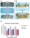
Overview of the system components and clamping measurement results. (A) From top to bottom: the microfluidic device as manufactured using the casting assembly, the laser-cut acrylic wells (outlined in red), and the 3D-printed pump adapter for standard microfluidic fittings (all images are bottom views of the respective components). (B) Overview of clamping assembly components with illustration of how components were assembled for chamber height measurements. (C) Bar graph showing the height of the microfluidic chamber under unclamped and clamped conditions. The color scheme of the bar corresponds to the color scheme of the outline of the images in (A).
Figure 4
Figure 4
The microfluidic device setup for burst pressure measurements. (A) Top: fluid flow diagram of the burst pressure test setup. Bottom: The clamping setup with the pump adapter attached. Each inlet is fitted for a standard 1/4″-28 microfluidic nut-and-ferrule-style connector for 1/16″ OD PTFE tubing, and each outlet was fitted with a barbed connector for silicone tubing. After each chip was primed, the silicone tubing was clamped closely to conduct the burst pressure test. (B) The results of the burst pressure tests sorted by chip location (left, center, or right) on the device. The bars represent the mean value, with error bars showing SD. Each bar is labelled with the mean burst pressure.

Similar articles

Cited by

References

    1. Bhatia S.N., Ingber D.E. Microfluidic organs-on-chips. Nat. Biotechnol. 2014;32:760–772. doi: 10.1038/nbt.2989. - DOI - PubMed
    1. Carvalho D.J.T., Moroni L., Giselbrecht S. Clamping strategies for organ-on-a-chip devices. Nat. Rev. Mater. 2023;8:147–164. doi: 10.1038/s41578-022-00523-z. - DOI
    1. Anwar K., Han T., Kim S.M. Reversible sealing techniques for microdevice applications. Sens. Actuators B Chem. 2011;153:301–311. doi: 10.1016/j.snb.2010.11.002. - DOI
    1. Li P., Ma Z., Zhou Y., Collins D.J., Wang Z., Ai Y. Detachable Acoustophoretic System for Fluorescence-Activated Sorting at the Single-Droplet Level. Anal. Chem. 2019;91:9970–9977. doi: 10.1021/acs.analchem.9b01708. - DOI - PubMed
    1. Le Berre M., Crozatier C., Casquillas G.V., Chen Y. Reversible assembling of microfluidic devices by aspiration. Microelectron. Eng. 2006;83:1284–1287. doi: 10.1016/j.mee.2006.01.257. - DOI

LinkOut - more resources