

Research Progress of Aluminum Alloy Welding/Plastic Deformation Composite Forming Technology in Achieving High-Strength Joints
- PMID: 38138812
- PMCID: PMC10744470
- DOI: 10.3390/ma16247672
Research Progress of Aluminum Alloy Welding/Plastic Deformation Composite Forming Technology in Achieving High-Strength Joints
Abstract
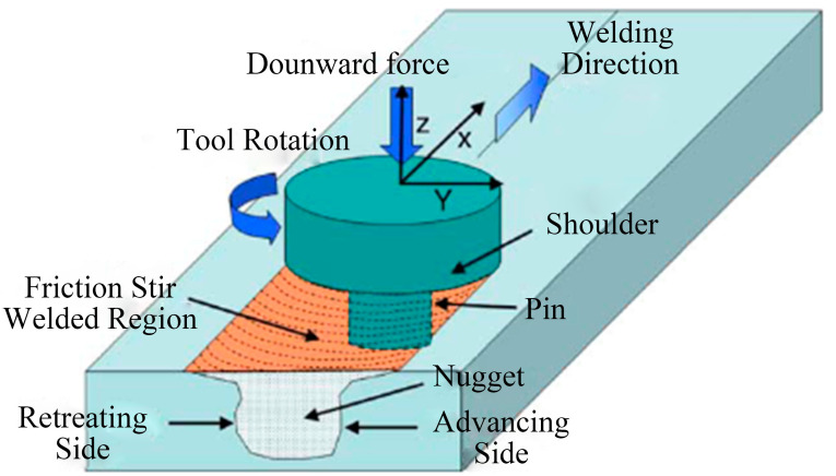
Fusion welding causes joint deterioration when joining aluminum alloys, which limits the use of aluminum alloy components in high-end equipment. This paper focuses on an overview of how to achieve high-strength aluminum alloy welded joints using welding/plastic deformation composite forming technology. The current technology is summarized into two categories: plastic deformation welding and plastic deformation strengthening. Plastic deformation welding includes friction stir welding, friction welding, diffusion welding, superplastic solid-state welding, explosive welding, and electromagnetic pulse welding. Plastic deformation strengthening refers to the application of plastic deformation to the weld seam or heat-affected zone, or even the whole joint, after welding or during welding, including physical surface modification and large-scale plastic deformation technology. Important processing parameters of plastic deformation welding and their effects on weld quality are discussed, and the microstructure is described. The effect of plastic deformation strengthening technology on the microstructure and performance evolution, including the hardness, tensile strength, fatigue property, residual stress, and hot cracking of aluminum alloy welded joints, and its evolution mechanism are systematically analyzed. Finally, this paper discusses the future development of plastic deformation strengthening technology and anticipates growing interest in this research area.
Keywords: aluminum alloy; mechanical property; plastic deformation strengthening; plastic deformation welding.
Conflict of interest statement
The authors declare no conflict of interest.
Figures


Similar articles
-
Study on the effect of high energy ultrasonic wave on MIG welding deformation and welding joint performance of LC52 aluminum alloy plate.Sci Rep. 2025 Apr 3;15(1):11466. doi: 10.1038/s41598-025-89545-5. Sci Rep. 2025. PMID: 40180964 Free PMC article.
-
Microstructure and Properties of Mg-Gd-Y-Zn-Mn High-Strength Alloy Welded by Friction Stir Welding.Materials (Basel). 2024 Aug 24;17(17):4190. doi: 10.3390/ma17174190. Materials (Basel). 2024. PMID: 39274580 Free PMC article.
-
The Effect of High-Temperature Deformation on the Mechanical Properties and Corrosion Resistance of the 2024 Aluminum Alloy Joint after Friction Stir Welding.Materials (Basel). 2024 Jun 17;17(12):2969. doi: 10.3390/ma17122969. Materials (Basel). 2024. PMID: 38930338 Free PMC article.
-
Review of Techniques for Improvement of Softening Behavior of Age-Hardening Aluminum Alloy Welded Joints.Materials (Basel). 2021 Oct 4;14(19):5804. doi: 10.3390/ma14195804. Materials (Basel). 2021. PMID: 34640203 Free PMC article. Review.
-
A Review on Friction Stir Welding of High-Strength Al-Zn-Mg Alloy: Insights on Second-Phase Particles.Materials (Basel). 2024 Oct 19;17(20):5107. doi: 10.3390/ma17205107. Materials (Basel). 2024. PMID: 39459812 Free PMC article. Review.
Cited by
-
Ultrasonic Non-Destructive Detection Method for Residual Stress in Rotary Forging Aluminum Alloy Plates.Materials (Basel). 2024 May 24;17(11):2528. doi: 10.3390/ma17112528. Materials (Basel). 2024. PMID: 38893792 Free PMC article.
-
Improvement of EMAT Butterfly Coil for Defect Detection in Aluminum Alloy Plate.Materials (Basel). 2025 Jul 7;18(13):3207. doi: 10.3390/ma18133207. Materials (Basel). 2025. PMID: 40649695 Free PMC article.
-
Investigation of the Strain-Stress Field in Nanoscale Multilayer Systems by the Phase Plane Method.Materials (Basel). 2024 May 20;17(10):2466. doi: 10.3390/ma17102466. Materials (Basel). 2024. PMID: 38793532 Free PMC article.
References
-
- Dubourg L., Merati A., Jahazi M. Process optimisation and mechanical properties of friction stir lap welds of 7075-T6 stringers on 2024-T3 skin. Mater. Des. 2010;31:3324–3330. doi: 10.1016/j.matdes.2010.02.002. - DOI
-
- Lequeu P., Smith K.P., Danielou A. Aluminum-Copper-Lithium Alloy 2050 Developed for Medium to Thick Plate. J. Mater. Eng. Perform. 2010;19:841–847. doi: 10.1007/s11665-009-9554-z. - DOI
-
- Mathers G. The Welding of Aluminium and Its Alloys. Woodhead Publishing Ltd.; Abington Hall, UK: 2002.
-
- Vargas J.A., Torres J.E., Pacheco J.A., Hernandez R.J. Analysis of heat input effect on the mechanical properties of Al-6061-T6 alloy weld joints. Mater. Des. 2013;52:556–564. doi: 10.1016/j.matdes.2013.05.081. - DOI
-
- Lu H., Shi L., Dong H., Li S., Guo D., Tao C. Influence of flame rectification on mechanical properties of Al–Zn–Mg alloy. J. Alloys Compd. 2016;689:278–286. doi: 10.1016/j.jallcom.2016.07.325. - DOI
Publication types
Grants and funding
LinkOut - more resources
Full Text Sources
