. 2023 Nov 6;10(12):4104-4111.
doi: 10.1021/acsphotonics.3c01104. eCollection 2023 Dec 20.

Chromatically Corrected Multicolor Multiphoton Microscopy

Affiliations

Chromatically Corrected Multicolor Multiphoton Microscopy

Hugo Blanc et al. ACS Photonics. .

Abstract

Simultaneous imaging of multiple labels in tissues is key to studying complex biological processes. Although strategies for color multiphoton excitation have been established, chromatic aberration remains a major problem when multiple excitation wavelengths are used in a scanning microscope. Chromatic aberration introduces a spatial shift between the foci of beams of different wavelengths that varies across the field of view, severely degrading the performance of color imaging. In this work, we propose an adaptive correction strategy that solves this problem in two-beam microscopy techniques. Axial chromatic aberration is corrected by a refractive phase mask that introduces pure defocus into one beam, while lateral chromatic aberration is corrected by a piezoelectric mirror that dynamically compensates for lateral shifts during scanning. We show that this light-efficient approach allows seamless chromatic correction over the entire field of view of different multiphoton objectives without compromising spatial and temporal resolution and that the effective area for beam-mixing processes can be increased by more than 1 order of magnitude. We illustrate this approach with simultaneous three-color, two-photon imaging of developing zebrafish embryos and fixed Brainbow mouse brain slices over large areas. These results establish a robust and efficient method for chromatically corrected multiphoton imaging.


Conflict of interest statement

The authors declare no competing financial interest.

Figures

Figure 1
Figure 1
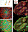
Chromatic aberration in dual-beam laser scanning microscopy. (a) Schematic representation of the imaging field of view. Due to axial chromatic aberration, at the center of the field of view (i) the two simulated focused beams centered at wavelengths λ1 and λ2 are shifted axially by ΔZλ12. Due to axial and lateral chromatic aberration, at the edge of the field of view (ii) and (iii) the two simulated focused beams are shifted axially by ΔZλ12 and laterally by ΔXλ12. (b) Measured lateral chromatic shifts ΔRλ12 = formula image between the two focused beams across the imaging field of view. The lateral shifts increase linearly with the distance from the center of the field of view. White dashed lines correspond to lateral shifts of 0.80 μm. Microscope objective used: Zeiss W Plan-Apochromat 20×/1.0 DIC (Zeiss 20×).
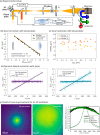
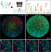
Figure 2
Figure 2
Chromatic aberration correction for dual-beam two-photon imaging. (a) Simplified optical setup of a two-photon point scanning microscope incorporating a pair of galvanometric mirrors optically conjugated with the back aperture of a microscope objective by a scan lens (SL) and tube lens (TL), a detection chain, and a module for dynamic chromatic aberration correction. The module consists of a phase mask, a piezo mirror, and two relay lenses. A complete schematic of the system is shown in Figure S1. (b, c) Axial chromatic correction with the refractive phase plate for two focused beams centered at wavelengths λ1 = 850 nm and λ2 = 1080 nm. By varying the amplitude (ΔZMask) and the shape of the phase mask etching profile, the axial position of one of the two beams (ΔZλ1) can be adjusted, while the axial resolution remains unchanged. (d) Dynamic correction of lateral chromatic aberration with the piezo mirror. The motion of the piezo mirror is synchronized with that of the linear galvanometer mirrors to compensate for the lateral chromatic shifts along the X and Y axes during the raster scanning of the two beams. (e) 2c–2P excitation efficiency across the imaging field of view with and without lateral chromatic correction. The field of view is 625 μm × 625 μm. White dashed lines indicate the areas where the fluorescence signal varies by less than 30%. Microscope objective used: Zeiss 20×.
Figure 3
Figure 3
Multicolor two-photon imaging of a live zebrafish embryo with dynamic chromatic correction. (a) Zebrafish embryos labeled with mCerulean, EGFP, and mCherry are mounted in an imaging chamber filled with 0.20% agarose and embryo medium for imaging. (b) Two-photon excitation spectra of the corresponding three fluorescent proteins and two-photon excitation wavelengths used for imaging (λ1 = 850 nm, λ2 = 1080 nm, and λ3 = 950 nm). (c, d) Maximal intensity projections computed from a 3D z-stack acquired over a field of view of 740 μm × 740 μm and a depth of 200 μm (c) without and (d) with lateral chromatic correction. (e) Series of ROIs extracted from 4D z-stacks acquired over the same volume with a time delay of 3 min. Red and blue arrows indicate cells undergoing division. Microscope objective used: Zeiss 20×.
Figure 4
Figure 4
Multicolor two-photon mosaic imaging in the cerebellum of a Brainbow transgenic mouse with dynamic chromatic correction. (a) Two-photon absorption spectra of the fluorescent proteins expressed by the Brainbow transgene (mTurquoise2, mEYFP, and tdTomato) and two-photon excitation wavelengths used for imaging (λ1 = 850 nm, λ2 = 1080 nm, and λ3 = 950 nm). (b, c) Individual tiles acquired on an area of 625 μm × 625 μm (b) without and (c) with lateral chromatic correction. (d, e) 5 × 5 mosaics of tiles acquired from a mouse brain cerebellum slice (d) without and (e) with lateral chromatic correction, corresponding to a scanned area of 2925 μm × 2950 μm. White dashed lines indicate tile borders. Microscope objective used: Zeiss 20×.

Similar articles

Cited by

References

    1. Wang M.; Da Y.; Tian Y. Fluorescent Proteins and Genetically Encoded Biosensors. Chem. Soc. Rev. 2023, 52 (4), 1189–1214. 10.1039/D2CS00419D. - DOI - PubMed
    1. Dumas L.; Clavreul S.; Michon F.; Loulier K. Multicolor Strategies for Investigating Clonal Expansion and Tissue Plasticity. Cell. Mol. Life Sci. 2022, 79 (3), 141.10.1007/s00018-021-04077-1. - DOI - PMC - PubMed
    1. Denk W.; Strickler J. H.; Webb W. W. Two-Photon Laser Scanning Fluorescence Microscopy. Science 1990, 248 (4951), 73–76. 10.1126/science.2321027. - DOI - PubMed
    1. Helmchen F.; Denk W. Deep Tissue Two-Photon Microscopy. Nat. Methods 2005, 2 (12), 932–940. 10.1038/nmeth818. - DOI - PubMed
    1. Grienberger C.; Giovannucci A.; Zeiger W.; Portera-Cailliau C. Two-Photon Calcium Imaging of Neuronal Activity. Nat. Rev. Methods Primers 2022, 2 (1), 66.10.1038/s43586-022-00147-1. - DOI - PMC - PubMed