Review
. 2024 Feb 27;24(5):1121-1134.
doi: 10.1039/d3lc00901g.

Innovative electrode and chip designs for transendothelial electrical resistance measurements in organs-on-chips

Affiliations
Review

Innovative electrode and chip designs for transendothelial electrical resistance measurements in organs-on-chips

Muriel A Holzreuter et al. Lab Chip. .

Abstract

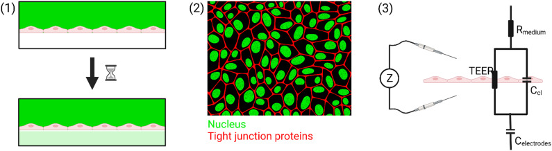
Many different epithelial and endothelial barriers in the human body ensure the proper functioning of our organs by controlling which substances can pass from one side to another. In recent years, organs-on-chips (OoC) have become a popular tool to study such barriers in vitro. To assess the proper functioning of these barriers, we can measure the transendothelial electrical resistance (TEER) which indicates how easily ions can cross the cell layer when a current is applied between electrodes on either side. TEER measurements are a convenient method to quantify the barrier properties since it is a non-invasive and label-free technique. Direct integration of electrodes for TEER measurements into OoC allows for continuous monitoring of the barrier, and fixed integration of the electrodes improves the reproducibility of the measurements. In this review, we will give an overview of different electrode and channel designs that have been used to measure the TEER in OoC. After giving some insight into why biological barriers are an important field of study, we will explain the theory and practice behind measuring the TEER in in vitro systems. Next, this review gives an overview of the state of the art in the field of integrated electrodes for TEER measurements in OoC, with a special focus on alternative chip and electrode designs. Finally, we outline some of the remaining challenges and provide some suggestions on how to overcome these challenges.


Conflict of interest statement

There are no conflicts to declare.

Figures

Fig. 1
Fig. 1. Overview of the different tools commonly used to assess the permeability of biological barriers. (1) Perfusion assay, (2) immunostaining, and (3) TEER. Figure created with https://BioRender.com.
Fig. 2
Fig. 2. Modelling the cell layer with an equivalent circuit. (1) Cell layer with equivalent circuit. Figure created with https://Biorender.com. (2) Complete vs. simplified equivalent circuit. Figure created with https://Biorender.com. (3) Typical impedance spectrum with the impedance (top) and phase shift (bottom). The left impedance spectrum shows the changes in response to different TEER values. The right impedance spectrum shows the changes in response to different cell layer capacitance values. (adapted from ref. , copyright 2018 Springer Nature, reproduced via Creative Commons Attribution license 4.0 (https://creativecommmons.org/licenses/by/4.0/)). (4) Simplified equivalent circuit of the chip used by van der Helm et al. in order to reduce the effects of confounding factors on the measurements. Reprinted from ref. , Copyright (2016), with permission from Elsevier.
Fig. 3
Fig. 3. Examples of conventional sandwich chips enabling TEER measurements. (1) CAD model and photograph of the TEER-chip designed by Henry et al. Reproduced from ref. with permission from the Royal Society of Chemistry. (2) Exploded schematic and photograph of the BBB-on-chip by Griep et al. with Pt wires for electrodes. Reproduced with permission from ref. , copyright 2012 Springer Nature. (3) Top: photograph of the BBB-on-chip by Matthiesen et al. The electrodes are integrated onto the membrane instead of above and below the channel. Bottom: schematic of the channel cross-section with current flow indication. Reproduced with permission from ref. . Copyright 2021 The Authors. Published by Wiley-VCH GmbH. (4) Exploded schematic of the TEER-MEA chip from Maoz et al. The chip includes electrodes above and below the membrane. Additionally, the bottom channel contains a MEA to measure the activity of electrically active cells. Reproduced from ref. with permission from the Royal Society of Chemistry. (5) Photograph (top) and exploded view (bottom) of the spatial-TEER (sTEER) device developed by Renous et al. The device features bottom electrodes that are fixed in position, as well as top electrodes that can be moved along the microfluidic channel to determine the TEER in different areas of the channel. In the exploded view, the assembly of the chip with its components is show: 1 – glass cover slip with patterned gold electrodes, 2 – bottom PDMS channel, 3 – permeable PC membrane, 4 – top PDMS channel, 5 – movable stainless steel electrodes, 6 – top PDMS layer. Reproduced and adapted from ref. with permission from the Royal Society of Chemistry.
Fig. 4
Fig. 4. Examples of multiplexed chips for TEER measurements. (1) BBB-on-chip by Palma-Florez et al. Left: brightfield microscopy of the hydrogel zone as well as the endothelial channel. Right: Live-dead staining of the cells in the endothelial channel. Scale bars 100 μm. Copyright 2023 Springer Nature, reproduced via Creative Commons Attribution license 4.0 (https://creativecommons.org/licenses/by/4.0). (2) Model of the blood–retinal barrier by Yeste et al. A: Schematic of the different cell layers of the blood–retinal barrier. B: Schematic of the chip design featuring a network of microgrooves to connect the different cell compartments. Electrodes for TEER measurements are patterned at the bottom of the microgrooves. Reproduced from ref. with permission from the Royal Society of Chemistry. (3) Illustration of the different layers and the assembled chip by Jeong et al. The chip contains four top and four bottom channels that intersect in 16 places. At each intersection, electrodes for TEER measurement are placed above and below the membrane. Reproduced with permission from ref. , copyright 2023 IEEE. (4) Confocal image of Caco-2 cells growing inside the commercial OrganoPlate (MIMETAS) as well as schematic of the electrode placement inside the media reservoirs. Reproduced from ref. , copyright 2021, with permission from the Royal Society of Chemistry via Creative Commons Attribution 3.0 Unported Licence (https://creativecommons.org/licenses/by/3.0/).

References

    1. Chitcholtan K. Asselin E. Parent S. Sykes P. H. Evans J. J. Exp. Cell Res. 2013;319:75–87. doi: 10.1016/j.yexcr.2012.09.012. - DOI - PubMed
    1. Maoz B. M. Herland A. FitzGerald E. A. Grevesse T. Vidoudez C. Pacheco A. R. Sheehy S. P. Park T.-E. Dauth S. Mannix R. Budnik N. Shores K. Cho A. Nawroth J. C. Segrè D. Budnik B. Ingber D. E. Parker K. K. Nat. Biotechnol. 2018;36:865–874. doi: 10.1038/nbt.4226. - DOI - PMC - PubMed
    1. Pineda E. T. Nerem R. M. Ahsan T. Cells Tissues Organs. 2013;197:399–410. doi: 10.1159/000346166. - DOI - PMC - PubMed
    1. Kimlin L. C. Casagrande G. Virador V. M. Mol. Carcinog. 2013;52:167–182. doi: 10.1002/mc.21844. - DOI - PubMed
    1. Elbakary B. Badhan R. K. S. Sci. Rep. 2020;10:3788. doi: 10.1038/s41598-020-60689-w. - DOI - PMC - PubMed

Publication types