[Preprint]. 2023 Dec 15:2023.12.14.571771.
doi: 10.1101/2023.12.14.571771.

Acute Neuropixels recordings in the marmoset monkey

Affiliations

Acute Neuropixels recordings in the marmoset monkey

Nicholas M Dotson et al. bioRxiv. .

Update in

Abstract

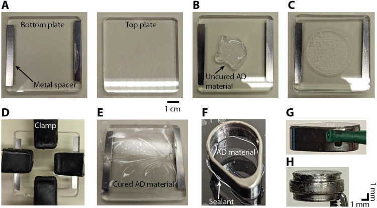
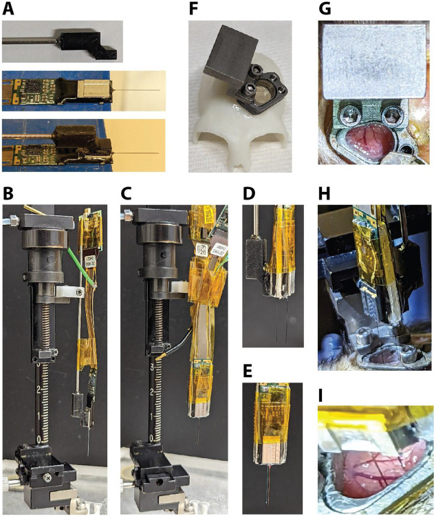
High-density linear probes, like Neuropixels, provide an unprecedented opportunity to understand how neural populations within specific laminar compartments contribute to behavior. Marmoset monkeys, unlike macaque monkeys, have a lissencephalic (smooth) cortex that enables recording perpendicular to the cortical surface, thus making them an ideal animal model for studying laminar computations. Here we present a method for acute Neuropixels recordings in the common marmoset (Callithrix jacchus). The approach replaces the native dura with an artificial silicon-based dura that grants visual access to the cortical surface, which is helpful in avoiding blood vessels, ensures perpendicular penetrations, and could be used in conjunction with optical imaging or optogenetic techniques. The chamber housing the artificial dura is simple to maintain with minimal risk of infection and could be combined with semi-chronic microdrives and wireless recording hardware. This technique enables repeated acute penetrations over a period of several months. With occasional removal of tissue growth on the pial surface, recordings can be performed for a year or more. The approach is fully compatible with Neuropixels probes, enabling the recording of hundreds of single neurons distributed throughout the cortical column.


Figures

Figure 1:
Figure 1:. The near absence of sulci in the marmoset makes the cortex highly suitable for laminar recordings.
A) Trace drawings of the marmoset and macaque monkey brains illustrating their relative sizes and the differences in the prevalence of sulci. The marmoset cortex is mostly smooth, while the macaque cortex is highly convoluted making it difficult to record perpendicular to the surface in many locations of the cortex. B-C) Digital reconstructions (not to scale relative to each other) of coronal slices further illustrate the relative ease of making laminar recordings in the marmoset compared to the difficulties with performing laminar recordings in the macaque monkey. Cortical areas 8aV, 8aD, MT, MST, and LIP are highlighted to show the differences in position created by sulci. (Images in B and C are from the scalablebrainatlas.incf.org; Paxinos et. al., 2000; Van Essen, 2002; Tokuno et. al., 2009; Paxinos et. al., 2012; Bakker et. al., 2015)
Figure 2:
Figure 2:. Recording chamber components.
A) Image of circular recording chamber used for MT recordings (top view). B) Image of egg-shaped recording chamber used for PFC recordings (top view). C) Insert for PFC chamber (AD not attached). D) Chamber with the insert inside. E) Image of the silicone gasket used to seal the chamber. F) Image of the gasket on top of the chamber. G) Image of the cap for the PFC chamber. H) Image of the chamber with gasket, cap, and four screws fixing the cap in place (top view). I) Side view of the PFC chamber with gasket and cap. The scale bars on part (I) apply to all images.
Figure 3:
Figure 3:. Procedure for making the AD material and adhering it to the insert.
A) Two acrylic plates are used to cure the AD material into a thin sheet. Metal spacers are attached to the bottom plate (left) in order to create a gap of 400 μm between the two plates. B) Several milliliters of the uncured AD material (Shin-Etsu, KE-1300T) is applied to the bottom plate. C) The top plate is then pressed down on top of the bottom plate. D) Four hand clamps are used to secure the top plate to the bottom plate. To achieve a thinner AD thickness the clamps are placed towards the middle. This creates a thickness of 100 to 200 μm in the center. E) After 24 hours the cured AD material is in a thin sheet of the desired thickness. F) A thin bead of silicone sealant (DOWSIL, 734 flowable sealant) is applied to the bottom surface of the insert before gently pressing it down onto the AD material. G) Insert with AD attached. H) Image of the circular insert with AD attached. The bulging section in the middle of the round insert rests on a lip inside the round chamber. In G and H, the insert is oriented upside down with the AD material at the top.
Figure 4.
Figure 4.. Neuropixels recording setup.
A) A custom holder with a metal rod is glued to the base of the Neuropixels probe. Ground and reference wires are also attached. B) The rod is held by the clamp of the microdrive. Tape is used to control the cable and headstage. C) Example of double probe setup attached to microdrive (1.0 mm spacer). D) Side view and E) front view of double probe setup. F) 3D-printed skull model made from a CT scan with a chamber and insert (AD attached) and a microdrive mount attached. G) Photo of the microdrive mount when it is attached to the chamber. H) Photo of the double probe setup during the process of lowering the probes (1.9 mm spacer). I) Close-up view of the two probes while inserted in the cortex. Note the visible blood vessels that could be avoided during probe insertion.
Figure 5.
Figure 5.. Current source density (CSD) can be used to identify the input layer of the cortex.
Examples of CSD plots and spiking data from 3 recording sessions using Neuropixels probes. A) CSD plots (arb. units) with the input layer highlighted (green horizontal line). B) Average waveforms for each detected unit are shown at the relative depth and relative location (column 1 or column 2) on the probe (jittered for visibility). Number of isolated units: left (n = 215), middle (n = 255), and right (n = 144).
Figure 6.
Figure 6.. Reconstruction of recording locations.
Recording locations were identified by combining 3D models and images taken of the probe and chamber. A) CT scan after head post and chamber implant. B) 3D-model of skull created from CT scan. C) 3D-model of chamber. D) Chamber model aligned to the chamber on the 3D-model of skull. The chamber model is transparent with an orange outline. E) Image through chamber of 3D-brain model (Liu et. al., 2021; marmosetbrainmapping.org). Anterior (A), posterior (P), medial (M), and lateral (L) directions are indicated in the bottom right corner. F-G) A separate chamber is used as a reference to determine the probe location relative to the chamber. After each recording, the microdrive is mounted on a pedestal and chamber identical to the ones used for recording (F). A picture is taken from below and then annotated. The chamber references (white lines) and probe shank location (red circle) are placed on top of the reconstructed map of areas to identify the recording location (G). This particular recording session is likely in area 8aV. Double probe recording sessions are reconstructed in the same manner.

References

    1. Arieli A., Grinvald A., & Slovin H. (2002). Dural substitute for long-term imaging of cortical activity in behaving monkeys and its clinical implications. Journal of neuroscience methods, 114(2), 119–133. - PubMed
    1. Asaad W. F., & Eskandar E. N. (2008). A flexible software tool for temporally-precise behavioral control in Matlab. Journal of neuroscience methods, 174(2), 245–258. - PMC - PubMed
    1. Bakker R., Tiesinga P., & Kötter R. (2015). The scalable brain atlas: instant web-based access to public brain atlases and related content. Neuroinformatics, 13, 353–366. - PMC - PubMed
    1. Chen L. M., Heider B., Williams G. V., Healy F. L., Ramsden B. M., & Roe A. W. (2002). A chamber and artificial dura method for long-term optical imaging in the monkey. Journal of neuroscience methods, 113(1), 41–49. - PubMed
    1. Cloherty S. L., Yates J. L., Graf D., DeAngelis G. C., & Mitchell J. F. (2020). Motion perception in the common marmoset. Cerebral Cortex, 30(4), 2659–2673. - PMC - PubMed

Publication types