

Theory predicts 2D chiral polaritons based on achiral Fabry-Pérot cavities using apparent circular dichroism
- PMID: 38184645
- PMCID: PMC10771534
- DOI: 10.1038/s41467-023-44523-1
Theory predicts 2D chiral polaritons based on achiral Fabry-Pérot cavities using apparent circular dichroism
Abstract
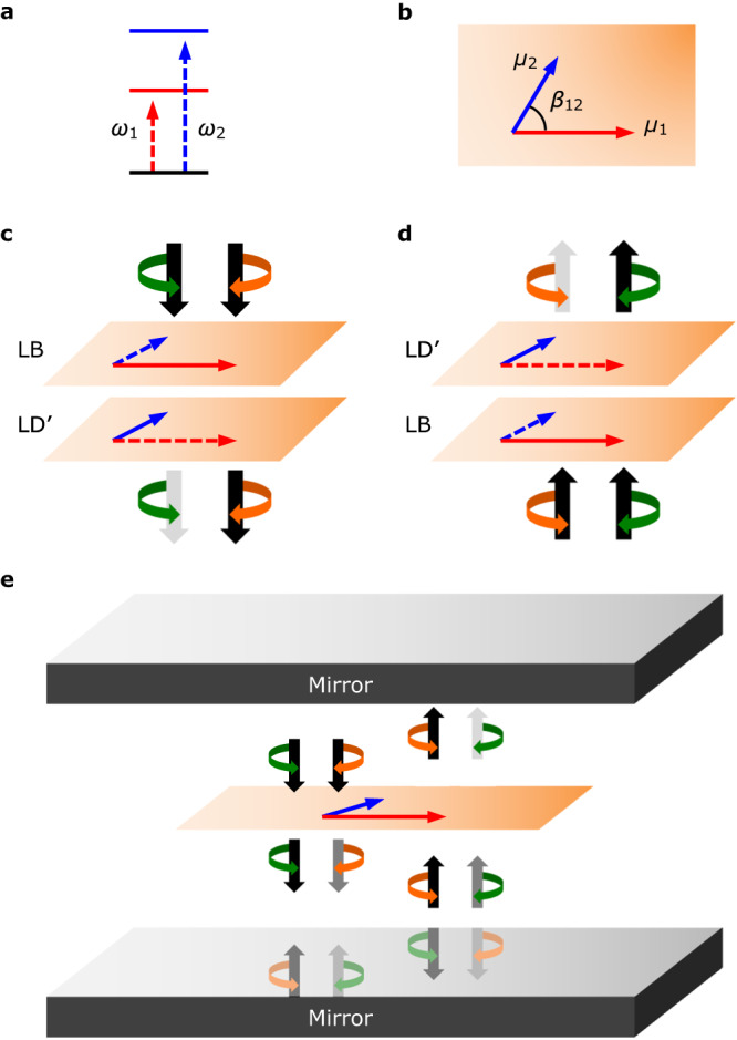
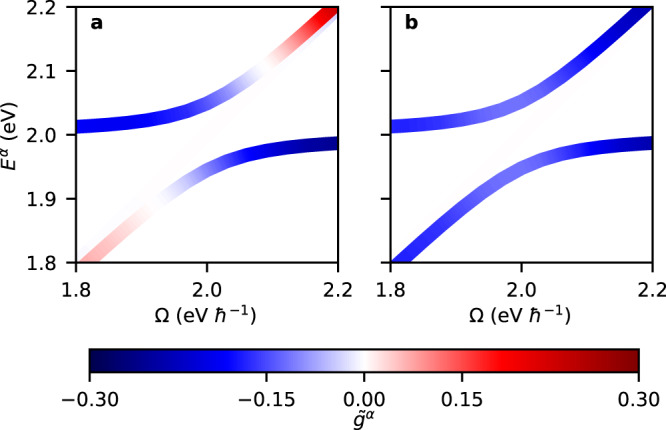
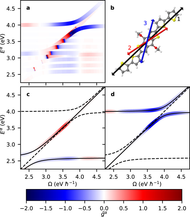
Realizing polariton states with high levels of chirality offers exciting prospects for quantum information, sensing, and lasing applications. Such chirality must emanate from either the involved optical resonators or the quantum emitters. Here, we theoretically demonstrate a rare opportunity for realizing polaritons with so-called 2D chirality by strong coupling of the optical modes of (high finesse) achiral Fabry-Pérot cavities with samples exhibiting "apparent circular dichroism" (ACD). ACD is a phenomenon resulting from an interference between linear birefringence and dichroic interactions. By introducing a quantum electrodynamical theory of ACD, we identify the design rules based on which 2D chiral polaritons can be produced, and their chirality can be optimized.
© 2024. The Author(s).
Conflict of interest statement
The authors declare no competing interests.
Figures
Similar articles
-
A 2D chiral microcavity based on apparent circular dichroism.Nat Commun. 2024 Apr 9;15(1):3072. doi: 10.1038/s41467-024-47411-4. Nat Commun. 2024. PMID: 38594293 Free PMC article.
-
Chiroptical Response Inversion and Enhancement of Room-Temperature Exciton-Polaritons Using 2D Chirality in Perovskites.Adv Mater. 2023 Oct;35(42):e2303203. doi: 10.1002/adma.202303203. Epub 2023 Sep 13. Adv Mater. 2023. PMID: 37587849
-
High-Chirality Polariton Lasing from Symmetry-Broken Plasmonic Lattices.ACS Nano. 2025 May 20;19(19):18824-18832. doi: 10.1021/acsnano.5c04290. Epub 2025 May 7. ACS Nano. 2025. PMID: 40332957
-
On-Chip High-Finesse Fabry-Perot Microcavities for Optical Sensing and Quantum Information.Sensors (Basel). 2017 Jul 31;17(8):1748. doi: 10.3390/s17081748. Sensors (Basel). 2017. PMID: 28758967 Free PMC article. Review.
-
Nanophotonic Platforms for Chiral Sensing and Separation.Acc Chem Res. 2020 Mar 17;53(3):588-598. doi: 10.1021/acs.accounts.9b00460. Epub 2020 Jan 8. Acc Chem Res. 2020. PMID: 31913015 Review.
Cited by
-
Molecular and solid-state topological polaritons induced by population imbalance.Nanophotonics. 2023 Jun 12;12(15):3109-3119. doi: 10.1515/nanoph-2023-0158. eCollection 2023 Jul. Nanophotonics. 2023. PMID: 39635050 Free PMC article.
-
A 2D chiral microcavity based on apparent circular dichroism.Nat Commun. 2024 Apr 9;15(1):3072. doi: 10.1038/s41467-024-47411-4. Nat Commun. 2024. PMID: 38594293 Free PMC article.
-
Circularly Polarized Microscopy of Thin Films of Chiral Organic Dyes.Chem Biomed Imaging. 2023 Jun 9;1(5):471-478. doi: 10.1021/cbmi.3c00049. eCollection 2023 Aug 28. Chem Biomed Imaging. 2023. PMID: 37655166 Free PMC article.
References
-
- Stobińska M, Alber G, Leuchs G. Perfect excitation of a matter qubit by a single photon in free space. EPL. 2009;86:14007. doi: 10.1209/0295-5075/86/14007. - DOI
-
- An J-H, Feng M, Oh CH. Quantum-information processing with a single photon by an input-output process with respect to low-Q cavities. Phys. Rev. A. 2009;79:032303. doi: 10.1103/PhysRevA.79.032303. - DOI
-
- Northup T, Blatt R. Quantum information transfer using photons. Nat. Photonics. 2014;8:356–363. doi: 10.1038/nphoton.2014.53. - DOI
Grants and funding
LinkOut - more resources
Full Text Sources
