Recovery bone formation on radiographic palatal bone dehiscences after incisor retraction with microimplants
- PMID: 38195052
- PMCID: PMC10893923
- DOI: 10.2319/081823-566.1
Recovery bone formation on radiographic palatal bone dehiscences after incisor retraction with microimplants
Abstract
Objectives: To investigate the difference in labial and palatal alveolar bone thickness and height during the retention period after incisor retraction treatment with microimplant.
Materials and methods: A sample of 21 patients (mean age: 17.80 ± 4.38 years) who underwent incisor retraction treatment using microimplants after premolar extraction was investigated. The cone-beam computed tomography images at pretreatment, posttreatment, and retention were used to measure anterior alveolar bone thickness (labial, palatal, and total; at three vertical levels) and height (labial and palatal) and differences in the incisor position during treatment or retention. Repeated-measures analysis of variance with Bonferroni correction was performed to compare the variables at T0, T1, and T2.
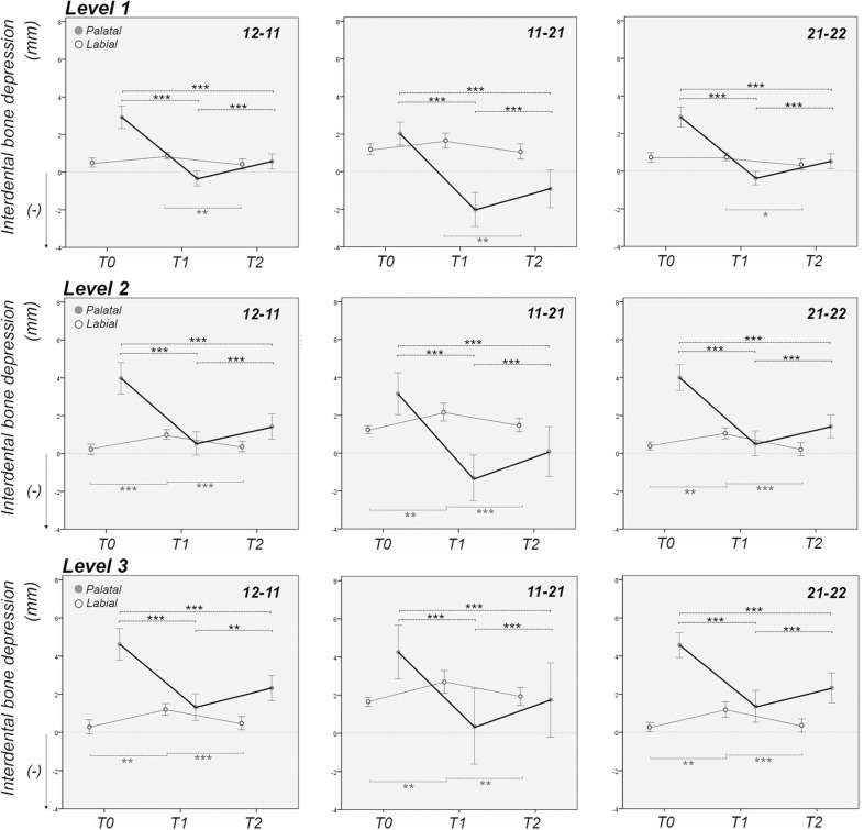
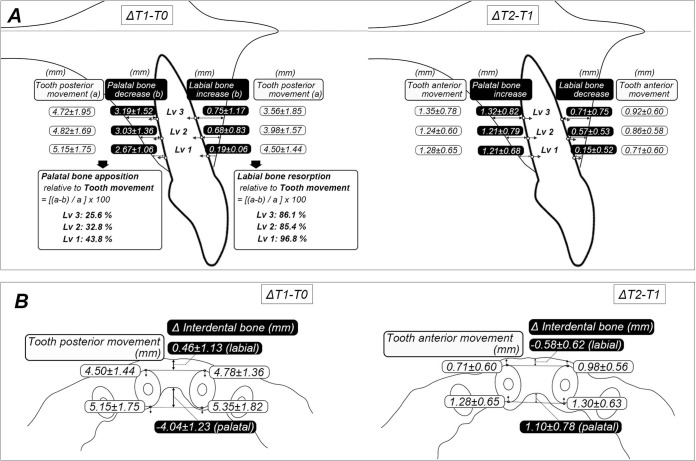
Results: The maxillary central incisor moved posteriorly by approximately 8.0 mm along with intrusive movement of 1.8 mm after treatment. The alveolar bone thickness significantly decreased on the palatal side and increased on the labial side after treatment. Thereafter, the palatal bone thickness significantly increased and labial bone thickness decreased during the retention period. The palatal interdental bone depressed by incisor retraction showed substantial bone deposition after retention.
Conclusions: Radiographic palatal bone dehiscences on the incisor root and palatal bone depression between the incisor roots were apparent after treatment. This palatal bone loss around the incisor roots noticeably recovered with newly formed bone during retention.
Keywords: Alveolar bone remodeling; Incisor retraction; Microimplant; Radiographic palatal bone dehiscence.
© 2024 by The EH Angle Education and Research Foundation, Inc.
Figures


References
-
- Nguyen T, Proffit WR. The decision-making process in orthodontics. In: Graber LW, Vanarsdall RL, Vig KWL, Huang GJ. eds. Orthodontics: Current Principles and Techniques 6th ed. St. Louis, Mo: Elsevier; 2017. 208–244
-
- Bae SM, Kim HJ, Kyung HM. Long-term changes of the anterior palatal alveolar bone after treatment with bialveolar protrusion, evaluated with computed tomography Am J Orthod Dentofacial Orthop 2018. 153 (1) 108–117 - PubMed
-
- Yanagita T, Kuroda S, Takano-Yamamoto T, Yamashiro T. Class III malocclusion with complex problems of lateral open bite and severe crowding successfully treated with miniscrew anchorage and lingual orthodontic brackets Am J Orthod Dentofacial Orthop 2011. 139 (5) 679–689 - PubMed
-
- Kim HJ, Jang WS, Park HS. Anatomical limits for distalization of lower posterior molars with micro-implant anchorage J Clin Orthod 2019. 53 (5) 305–313 - PubMed
MeSH terms
LinkOut - more resources
Full Text Sources