. 2024 Mar;23(3):377-382.
doi: 10.1038/s41563-023-01773-0. Epub 2024 Jan 9.

Parity-time-symmetric photonic topological insulator

Affiliations

Parity-time-symmetric photonic topological insulator

Alexander Fritzsche et al. Nat Mater. 2024 Mar.

Abstract

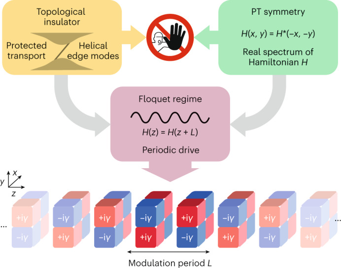
Topological insulators are a concept that originally stems from condensed matter physics. As a corollary to their hallmark protected edge transport, the conventional understanding of such systems holds that they are intrinsically closed, that is, that they are assumed to be entirely isolated from the surrounding world. Here, by demonstrating a parity-time-symmetric topological insulator, we show that topological transport exists beyond these constraints. Implemented on a photonic platform, our non-Hermitian topological system harnesses the complex interplay between a discrete coupling protocol and judiciously placed losses and, as such, inherently constitutes an open system. Nevertheless, even though energy conservation is violated, our system exhibits an entirely real eigenvalue spectrum as well as chiral edge transport. Along these lines, this work enables the study of the dynamical properties of topological matter in open systems without the instability arising from complex spectra. Thus, it may inspire the development of compact active devices that harness topological features on-demand.


Conflict of interest statement

The authors declare no competing interests.

Figures

Fig. 1
Fig. 1. Conceptual idea of a PT-symmetric topological insulator.
Conventional wisdom regards topological insulators and PT symmetry as mutually exclusive concepts. Distributing gain and loss (±iγ, indicated as red (+) and blue (–), respectively) dynamically along the spatial degrees of freedom x and y and the evolution coordinate z of a periodically modulated system allows for the construction of a complex Floquet drive that overcomes this dichotomy by simultaneously supporting topologically protected edge transport and an entirely real eigenvalue spectrum in a genuinely non-Hermitian arrangement.
Fig. 2
Fig. 2. Non-Hermitian Floquet driving protocol and band structure.
a, As a PT-symmetric generalization of the anomalous Z2 drive, our protocol consists of six distinct steps in which individual pairs of sites are allowed to interact. Note that only excitations in the two sites residing near the obtuse-angle (135°) corners of the rhombic unit cell (marked by a green dashed outline) populate the chiral edge states of the driven lattice, whereas excitations of the other two sites near the acute-angle (45°) corners result in closed loops. The individual sites of the two sublattices, A and B, are indicated by black and white-filled circles, respectively, while the presence of gain and loss is highlighted by red and blue haloes, respectively. b, The left side shows the numerically calculated bulk band structure as function of the quasimomenta kx and ky for full intra-sublattice coupling (solid connecting lines in steps 1, 3, 4 and 6 of a) and 66% inter-sublattice coupling (dashed connecting lines in steps 2 and 5 of a). Here, a denotes the lattice constant. The blue-shaded surface represents the real part of the quasi-energy ε. The intact PT symmetry of the arrangement is evidenced by the globally vanishing imaginary (Imag) part (orange). The right side shows that in addition to the projection of the bulk bands (blue), the edge band structure (numerically calculated for a semi-infinite ribbon) exhibits a pair of dispersion-free counter-propagating chiral edge states (dotted magenta lines) that likewise feature entirely real eigenvalues.
Fig. 3
Fig. 3. Photonic implementation and bulk excitations.
a, Schematic of the three-dimensional wave guide mesh lattice that implements the proposed protocol in an entirely passive setting. Shown is one transverse unit cell as well as the sections of wave guides from the adjacent unit cells it interacts with in the course of the driving cycle. The sublattices A and B are indicated by the respective colours (dark/light grey) of the wave guides, and the regions with deliberately introduced losses are shaded purple. More details are provided in Supplementary Fig. 2. b, Experimentally observed intensity output patterns at the output facet of the sample resulting from single-site bulk excitations in a lattice composed of 3 × 4 unit cells. As a guide to the eye, positions of the wave guides of this lattice are indicated by grey circles, whereas the four different initially excited wave guides of a bulk unit cell (green rhombus) are highlighted with orange circles. Note that in each case, the wave packets are subject to substantial bulk diffraction (highlighted by the orange arrows) enabled by the fractional inter-sublattice couplings in steps 2 and 5 of the driving protocol. Simulations of the degree of bulk localization for different inter-sublattice couplings are provided in Supplementary Fig. 4. Source data
Fig. 4
Fig. 4. Counter-propagating topological edge states.
a,b, Tracking the pair of counter-propagating topological edge channels associated with the two sublattices (dashed magenta outlines). Shown are the intensity distributions after two driving periods as observed at the output facet of the sample when injecting light into specific edge sites (highlighted in orange). Note that, while both channels flow along the outermost sites of the x edges (orange arrows), their paths are offset by half a unit cell (green rhombus) along the y edges. As a result, the clockwise-propagating channel of sublattice A shifts to bypass the deliberately induced defect in the lower right-hand corner (right panel of a), while the channel of sublattice B remains unaffected. c, EOR (fraction of the overall intensity contained in the edge channels) for a single-site edge (0.56 ± 0.03, right panel) and bulk excitations (0.36 ± 0.02, left panel). d, The chiral nature of topological transport in our system is clearly demonstrated by the ratio of 0.83 ± 0.03 between the intensities of the five leading versus trailing edge channel sites for each injection location evaluated for the entire set of edge excitations. The insets in c and d schematically indicate the bulk/edge excitation positions included in the analysis for the respective panels. Source data

References

    1. Klitzing, K. V., Dorda, G. & Pepper, M. New method for high-accuracy determination of the fine-structure constant based on quantized Hall resistance. Phys. Rev. Lett.45, 494–497 (1980).10.1103/PhysRevLett.45.494 - DOI
    1. Kane, C. L. & Mele, E. J. Z2 topological order and the quantum spin Hall effect. Phys. Rev. Lett.95, 146802 (2005). 10.1103/PhysRevLett.95.146802 - DOI - PubMed
    1. Bernevig, B. A. & Zhang, S. C. Quantum spin Hall effect. Phys. Rev. Lett.96, 106802 (2006). 10.1103/PhysRevLett.96.106802 - DOI - PubMed
    1. König, M. et al. Quantum spin Hall insulator state in HgTe quantum wells. Science318, 766–770 (2007). 10.1126/science.1148047 - DOI - PubMed
    1. Haldane, F. D. M. Model for a quantum Hall effect without Landau levels: condensed-matter realization of the ‘parity anomaly’. Phys. Rev. Lett.61, 2015–2018 (1988). 10.1103/PhysRevLett.61.2015 - DOI - PubMed

LinkOut - more resources