[Preprint]. 2023 Dec 22:rs.3.rs-3665801.
doi: 10.21203/rs.3.rs-3665801/v1.

Skin-inspired, sensory robots for electronic implants

Affiliations

Skin-inspired, sensory robots for electronic implants

Wubin Bai et al. Res Sq. .

Update in

  • Skin-inspired, sensory robots for electronic implants.
    Zhang L, Xing S, Yin H, Weisbecker H, Tran HT, Guo Z, Han T, Wang Y, Liu Y, Wu Y, Xie W, Huang C, Luo W, Demaesschalck M, McKinney C, Hankley S, Huang A, Brusseau B, Messenger J, Zou Y, Bai W. Zhang L, et al. Nat Commun. 2024 Jun 5;15(1):4777. doi: 10.1038/s41467-024-48903-z. Nat Commun. 2024. PMID: 38839748 Free PMC article.

Abstract

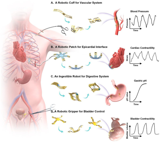
Living organisms with motor and sensor units integrated seamlessly demonstrate effective adaptation to dynamically changing environments. Drawing inspiration from cohesive integration of skeletal muscles and sensory skins in these organisms, we present a design strategy of soft robots, primarily consisting of an electronic skin (e-skin) and an artificial muscle, that naturally couples multifunctional sensing and on-demand actuation in a biocompatible platform. We introduce an in situ solution-based method to create an e-skin layer with diverse sensing materials (e.g., silver nanowires, reduced graphene oxide, MXene, and conductive polymers) incorporated within a polymer matrix (e.g., polyimide), imitating complex skin receptors to perceive various stimuli. Biomimicry designs (e.g., starfish and chiral seedpods) of the robots enable various motions (e.g., bending, expanding, and twisting) on demand and realize good fixation and stress-free contact with tissues. Furthermore, integration of a battery-free wireless module into these robots enables operation and communication without tethering, thus enhancing the safety and biocompatibility as minimally invasive implants. Demonstrations range from a robotic cuff encircling a blood vessel for detecting blood pressure, to a robotic gripper holding onto a bladder for tracking bladder volume, an ingestible robot residing inside stomach for pH sensing and on-site drug delivery, and a robotic patch wrapping onto a beating heart for quantifying cardiac contractility, temperature and applying cardiac pacing, highlighting the application versatilities and potentials of the nature-inspired soft robots. Our designs establish a universal strategy with a broad range of sensing and responsive materials, to form integrated soft robots for medical technology and beyond.


Conflict of interest statement

Additional Declarations: There is NO Competing Interest.

Figures

Figure 1
Figure 1. Schematic illustration showing nature-inspired sensory robots as minimally invasive smart implants for diagnosis, stimulation, and drug delivery.
(A) A robotic cuff for vascular system. The twisting motion provides physical enclosing around a blood vessel for precise detection of blood pressure and structural support. (B) A robotic patch for epicardial interface. The gripping motion enables gentle contact with a beating heart without residual straining, to provide real-time quantification of cardiac contractility and temperature, and apply coordinated electrical stimulation for cardiac pacing. (C) An ingestible robot for digestive system. This structural transition from the shape of a miniaturized pill to a 3D expanded hoop enables extended stay inside stomach to provide both pH sensing and drug delivery. (D) A robotic gripper for bladder control. The adaptive motion of gripping onto a bladder provides precise tracking of bladder volume and targeted stimulation to sacral nerve for treating urological disorders.
Figure 2
Figure 2. Multi-materials Integration for Multi-modal Sensory Soft Robot.
(A) Schematic illustration of epidermis-dermis-muscle structure of skin. (B) Nature-inspired structure of soft robot from skin. (C) Conceptual illustration of the integrated multi-modal sensory soft robot with distinct nanocomposite sensors functionalized into each arm. (D) Schematic illustration of a multi-modal sensory soft robot with a nature-inspired starfish design. Left: schematic illustration on an exploded view of the robot, highlighting 3 primary constituent layers, including a flexible multi-modal layer, a bio-adhesive layer, and an actuation hydrogel layer. Right: Schematic illustration highlighting the multi-material integration within the multi-modal layer including: (i) A nanocomposite of silver nanowires (AgNWs) and polyimide (PI) as a flexible heater; (ii) A nanocomposite of AgNWs and PDMS as a strain sensor; (iii), A nanocomposite of reduced graphene oxide (RGO) and PI as a temperature sensor; (iv), A nanocomposite of poly(3,4-ethylenedioxythiophene) polystyrene sulfonate (PEDOT:PSS) and PI as sensing and stimulation electrodes. (E) Optical image of the fabricated flexible multi-modal e-skin functionalized with six nanocomposite sensors. (F&G) Optical image showing conformal attachment of the soft sensory robot onto human skin (F) and porcine tissue (G) with high mechanical compliance. (H) Top: Schematic illustration showing a temperature-responsive bending behavior resulted from a bilayer design using poly(N-isopropylacrylamide) (PNIPAM) and polyimide-based nanocomposite. Bottom: The volumetric shrinkage of PNIPAM at various temperatures during heating process. (I-K) Optical images and corresponding finite element modeling of structural reconfiguration of soft sensory robots upon a thermal trigger. The colors in the legend indicate the magnitude of the von Mises stress in the configurations. (I) Biomimicry soft gripper undergoes enclosing motion upon heating at 40 °C. (J) A soft sensory robot inspired by chiral seedpods undergoes a helix reversal upon heating at 40 °C. (K) A soft robotic pill based on an anchored hydrogel/nanocomposite tri-layer structure undergoes expanding motion upon heating at 40 °C. (L&M) Schematic illustration and optical images of representative examples of anisotropic integration of various functional materials into a polymeric matrix to form a multi-modal sensing system using a solution-based approach. (L) A RGO/PI-based temperature sensor and an AgNW/PI-based heater integrated on the same side of a polyimide layer. (M) PEDOT:PSS/PI-based electrodes and RGO/PI temperature sensors integrated on the two opposite sides of a polyimide layer, respectively. Scale bars, 5mm.
Figure 3
Figure 3. Anisotropic integration of nanocomposites for on-demand robotic actuation with spatiotemporal control.
(A&B) Schematic illustration showing an exploded view (A) and optical image (B) of a soft robotic arm comprising a PNIPAM hydrogel layer, a thermal sensor based on RGO/PI nanocomposite, and an actuation heater based on AgNW/PI nanocomposite. The hydrogel is bonded onto the multi-functional nanocomposite layer via n-butyl cyanoacrylate adhesive. Joule heating generated by the electrical heater based on AgNW/PI nanocomposite triggers the robotic actuation of the PNIPAM hydrogel to bend the robotic arm. Scale bar, 5mm. (C&D) SEM images of nanocomposite films used in constructing the sensory robots. Here, deep reactive ion etching (DRIE) of partial regions of the nanocomposite films reveals the anisotropic integration within the films where the pristine PI regions form clear boundaries with AgNW/PI regions (C), and RGO/PI regions (D), respectively. In the nanocomposite regions, nearly all the AgNWs or RGO are uniformly dispersed inside the PI matrix, as AgNWs and RGO have higher surface-free energy than that of PI, leading to excellent wetting behavior and high binding strength inside PI. Scale bars, (C) 1.5 μm, (D) 10 μm. (E) Infrared thermograph of an AgNW/PI-based heater undergoing bending and twisting motions. The nanocomposite heater exhibits consistent heating performance after 1000 bending and twisting cycles (Fig. S18). (F) Surface temperature of the AgNW/PI-based heater as a function of the input electric power. Notably, the AgNW/PI nanocomposite heater can function under relatively low input electric power. (G) The resultant bending angle of a soft robotic arm as a function of the input electric power. (H) Resistive response at various temperatures ranging from 23 °C to 92 °C, for the RGO/PI-based thermal sensor undergoing bending and twisting motions, and immersed in a solution of PBS. (I) Static cycling test of the RGO/PI-based thermal sensor. (J) Resistive response of the MXene- based thermal sensor for temperature ranging from 23 °C to 55 °C. (K) Temperature measurement on the MXene/PI thermal sensor and a commercial thermal resistor (ERT-J0ET102H ). (L) Stepwise actuation of coiling via sequential thermal stimulus. Fig. S25 describes the fabrication strategy of integrating AgNW/PI-based heaters and RGO/PI-based thermal sensors into a single flexible film compatible to serve as part of the bilayer design of the sensory robot. Top: Infrared thermograph of AgNW/PI-based heaters via sequential power input. Bottom: Optical images showing the corresponding structural change of the soft robotic probe from a flat state to a coiled state upon sequential thermal activation. Scale bars, 10mm. (M) The integrated RGO/PI-based thermal sensors enable temperature measurement of localized regions to realize proprioceptive sensing. (N) Optical images demonstrating the on-demand motion control of a three-arm soft robotic gripper via sequentially programming input power. Scale bars, 5mm.
Figure 4
Figure 4. Design and construction of a soft sensory robot for wireless sensing and actuation.
(A) Schematic illustration of a soft sensory robot constructed with an electrical heater, a polyacrylamide (PAAm)-based pressure sensor, and two inductive coils for transmission sensing signals (B) and electrical power (C), respectively. (B) Exploded view of the sensing components containing a capacitor formed by two electrodes, a PAAm-hydrogel dielectric layer, and an inductive communication coil made of copper (Cu). (C) Exploded view of the actuation components primarily consisting of a PNIPAM actuation hydrogel, a flexible electrical heater, and a radio-frequency (RF) power harvester based on a copper coil. (D) Equivalent circuit diagram of the component for wireless pressure sensing. Connecting the pressure-sensing capacitor to an inductor coil forms an LC resonance circuit, where the pressure change on the capacitor leads to the capacitive change and translates to the change of characteristic resonance frequency of the LC circuit, which can be captured by an external probing coil connected to a vector network analyzer (VNA) to realize the wireless sensing function. (E) Equivalent circuit diagram of the component for wireless actuation, A transmitting coil connected to an RF power amplifier delivers energy to the receiving coil of the sensory robot, which transmits an electric current to the heater that actuates the robotic motion. (F) Measured capacitive change of the PAAm-based pressure sensor in response to applied pressure. (G) Measured shift of resonance curves of the PAAm-based pressure sensor in response to applied pressure. (H) Change of the LC resonant frequency as a function of applied pressure serving as a signal-transduction scheme for wireless pressure detection. (I) Thermal distribution of the electrical heater and the receiving inductor while wirelessly harvesting energy. The results exhibit minimal heating in the receiving coil with most of the transmitted power consumed by the electrical heater, demonstrating the capability for minimum heat damage to surrounding bio-environments and efficient energy usage. (J) Optical images of a soft sensory robot undergoing a wireless actuation to transform from a flat state to a bent state. (K) The output power as a function of frequency, showing the optimized frequency is ~15 MHz. (L) The output electrical power as a function of the input power. (M) The temperature change of the electrical heater overtime under various output powers used for wireless actuation. (N) Optical images of the deformed RF coils including bending, twisting and distorting. (0) The resonance frequency changes of RF coil under various shape deformations. Here the bending angle 0 is 60°. Scale bars, 5mm.
Figure 5
Figure 5. Soft sensory robots interfacing with various internal organs.
(A) Schematic illustration of a fully implantable, soft robotic gripper gently holding a bladder for precise measurement of bladder volume and providing electrical stimulation in a wireless closed-loop control fashion. (B) The control platform consists of a wireless power harvesting network, a full bridge amplifier, a voltage regulator, a signal conditioning circuit for strain sensors, a Bluetooth System-on-Chip, and a MOSFET switch for amplification of electrical stimulation. (C) System block diagram of the wireless closed-loop controlled bladder electrical stimulation module. Fig. S47A illustrates the structural design of the soft robotic gripper composed of bilayer actuators and buckled strain sensors. (D) Demonstration of the soft robotic gripper deployed onto an artificial bladder based on a balloon undergoing repetitive transformations from a deflating state to an inflating state. Here, the 3D buckled strain sensor attached onto the balloon enables real-time detection of bladder volume as shown in Fig. S47B. (E) Measured resistive characteristics of the buckled strain sensor on the artificial bladder as a function of the bladder volume. (F) Representative test of the 3D buckling strain sensor in real-time monitoring of volumetric change of the artificial bladder during cyclic movements of filling and emptying. (G) Programmed electrical stimulation (top) and measured volume of an artificial bladder based on a balloon (middle and bottom). The experimental demonstration is conducted using the following parameters: volume threshold of ~100 mL, electrical stimulation amplitude of 3 V. (H) Schematic illustration of a soft robotic cuff integrated with a strain sensor enclosing around a blood vessel for monitoring blood pressure. Fig. S50A shows the layout of the soft robotic cuff. (I) Top: Optical image of a soft robotic cuff wrapping around an artificial vessel made by a rubbery tube through which water is pumped to stimulate blood circulation. Bottom: Enlarged view of the robotic cuff highlighting the integrated strain sensor made of a serpentine Au/PI resistor for measuring blood pressure. (J) Measured resistive change of the strain sensor at various simulated blood pressures. (K) Representative measurement of fluidic pressure of the artificial artery system using the soft robotic cuff. (L) Schematic illustration of a soft ingestible robot designed for continuous monitoring of pH and extended drug delivery inside the stomach. The robot consists of the actuation layer (bilayers of PNIPAM and functional nanocomposites), drug-releasing layer (PLGA/rhodamine-B patch composite), and the pH sensing layer (PEDOT:PSS/PVA hydrogel) as shown in Fig. S51A (M) Optical images showing the soft ingestible robot entering (top), expanding and blocking (bottom) in the stomach. This engineering design enables the drug patch and pH sensor extensively retained inside stomach to enhance the efficiency and precision of drug release and pH monitoring. (N) Electrical response of PEDOT:PSS/PVA hydrogel to pH change ranging from 3 to 7 over time. (0) Here, rhodamine-B is used as a model substance that is embedded into the poly lactic-co-glycolic acid (PLGA) matrix to form a drug delivery patch concealed inside the robot. The UV-vis absorbance spectrum is used to measure the concentration of the rhodamine-B released from the robot in 1 h under various temperatures which dictate the robotic motion and further affect the exposure area of the drug patch to the gastric fluid. Scale bars, 5mm.
Figure 6
Figure 6. in vivo validation of a soft robotic thera-gripper for epicardial sensing and pacing.
(A) Confocal microscope images of 3T3-J-2 cells before (control) and after exposure to as-prepared soft robots integrated with an e-skin layer and a PNIPAM hydrogel-muscle layer, incubated at 37 °C and 39 °C for 48h. Scale bars, 50 μm. (B) Comparative cell viability before and after soft robot’s exposure, indicating that 3T3-J-2 cells exposed with the as-prepared soft robot high and cultured at the elevated temperature (39 °C) have no decreased viability. Scale bars, 50 μm. (C) Schematic illustration showing the thera-gripper features minimally invasive insertion at the resting state and wraps onto the surface of a beating heart at the actuation state. The thera-gripper contains four strain sensors made of serpentine Au/PI resistors, two pacing electrodes based on Au, and two temperature sensors made of thermal resistors. An exploded schematic view of the soft robotic thera-gripper is shown in Fig. S52A. (D) Finite element modeling of the actuation state. The colors in the legend indicate the magnitude of the von Mises stress. (E) Image of a soft robotic thera-gripper grasping on the epicardial surface of a living mouse heart. Scale bar, 5mm. (F) Temperature measurements from the thera-gripper during its deployment onto the mouse heart. (G) The surface ECG trace during electrical stimulation using a pair of Au pacing electrodes. Fig. S52D shows the representative voltage traces of the ECG under electrical stimulation with different voltages, offering great potential for selectively and locally pacing the cardiac cells to restore normal heart function. (H&l) Optical images of a healthy heart (H) and heart two weeks after myocardial infarction (Ml) (I). The Ml area is shown by the white dashed circle in (I). Fig. S63B shows the post-MI ECG signals with hyperacute T waves. (J&K) M-mode echocardiographic images from a healthy (J) and post-MI heart (K). (L) Schematic illustration showing the thera-gripper position on a mouse heart, where the strain sensors (labeled as SI, S2, S3, and S4) are located onto different heart chambers for locally monitoring of dysfunctional tissue. (M&N) Representative measurements of local cardiac contractions before (M) and after myocardial infarction (N) using a soft robotic thera-gripper wrapping onto a living mouse heart.

References

    1. Xiao X., Xiao X., Lan Y., Chen J., Learning from nature for healthcare, energy, and environment, Innov. 2 (2021) 100135. https://doi.org/10.1016/j.xinn.2021.100135. - DOI - PMC - PubMed
    1. Wolf C., Linden D.E.J., Biological pathways to adaptability – interactions between genome, epigenome, nervous system and environment for adaptive behavior, Genes, Brain Behav. 11 (2012) 3–28. https://doi.org/10.1111/j.1601-183X.2011,00752.x. - DOI - PubMed
    1. Ren L., Li B., Wei G., Wang K., Song Z., Wei Y., Ren L., Liu Q., Biology and bioinspiration of soft robotics: Actuation, sensing, and system integration., IScience. 24 (2021) 103075. 10.1016/j.isci.2021.103075. - DOI - PMC - PubMed
    1. Bartolozzi C., Natale L., Nori F., Metta G., Robots with a sense of touch, Nat. Mater. 15 (2016) 921–925. 10.1038/nmat4731. - DOI - PubMed
    1. Johansson R.S., Flanagan J.R., Coding and use of tactile signals from the fingertips in object manipulation tasks, Nat. Rev. Neurosci. 10 (2009) 345–359. 10.1038/nrn2621. - DOI - PubMed

Publication types

LinkOut - more resources