

Research Progress of Electrically Driven Multi-Stable Cholesteric Liquid Crystals
- PMID: 38203989
- PMCID: PMC10779722
- DOI: 10.3390/ma17010136
Research Progress of Electrically Driven Multi-Stable Cholesteric Liquid Crystals
Abstract
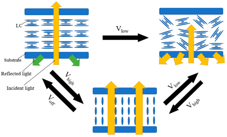
Electrically driven multi-stable cholesteric liquid crystals can be used to adjust the transmittance of incident light. Compared with the traditional liquid crystal optical devices, the multi-stable devices only apply an electric field during switching and do not require a continuous electric field to maintain the various optical states of the device. Therefore, the multi-stable devices have low energy consumption and have become a research focus for researchers. However, the multi-stable devices still have shortcomings before practical application, such as contrast, switching time, and mechanical strength. In this article, the latest research progress on electrically driven multi-stable cholesteric liquid crystals is reviewed, including electrically driven multi-stable modes, performance optimization, and applications. Finally, the challenges and opportunities of electrically driven multi-stable cholesteric liquid crystals are discussed in anticipation of contributing to the development of multi-stable liquid crystal devices.
Keywords: bistable mode; cholesteric phase; electrical driving mode; liquid crystals; multi-stability; multi-stable mode; optical devices; tri-stable mode.
Conflict of interest statement
The authors declare no conflict of interest.
Figures


Similar articles
-
Beyond Color Boundaries: Pioneering Developments in Cholesteric Liquid Crystal Photonic Actuators.Micromachines (Basel). 2024 Jun 20;15(6):808. doi: 10.3390/mi15060808. Micromachines (Basel). 2024. PMID: 38930778 Free PMC article. Review.
-
A bistable cholesteric liquid crystal film stabilized by a liquid-crystalline epoxy/thiol compound-based polymer.Phys Chem Chem Phys. 2023 Aug 23;25(33):22325-22335. doi: 10.1039/d3cp02613b. Phys Chem Chem Phys. 2023. PMID: 37578327
-
Electrically switchable multi-stable cholesteric liquid crystal based on chiral ionic liquid.Opt Lett. 2014 Dec 15;39(24):6795-8. doi: 10.1364/OL.39.006795. Opt Lett. 2014. PMID: 25502999
-
Fast bistable switching of a cholesteric liquid crystal device induced by application of an in-plane electric field.Appl Opt. 2014 Nov 1;53(31):7321-4. doi: 10.1364/AO.53.007321. Appl Opt. 2014. PMID: 25402894
-
A Review of Developments in Polymer Stabilized Liquid Crystals.Polymers (Basel). 2023 Jul 6;15(13):2962. doi: 10.3390/polym15132962. Polymers (Basel). 2023. PMID: 37447607 Free PMC article. Review.
Cited by
-
Beyond Color Boundaries: Pioneering Developments in Cholesteric Liquid Crystal Photonic Actuators.Micromachines (Basel). 2024 Jun 20;15(6):808. doi: 10.3390/mi15060808. Micromachines (Basel). 2024. PMID: 38930778 Free PMC article. Review.
-
Electro-Optic Response of Polymer-Stabilized Cholesteric Liquid Crystals with Different Polymer Concentrations.Polymers (Basel). 2024 Aug 28;16(17):2436. doi: 10.3390/polym16172436. Polymers (Basel). 2024. PMID: 39274069 Free PMC article.
-
Recent Advances in Soft Matter.Materials (Basel). 2025 Mar 25;18(7):1440. doi: 10.3390/ma18071440. Materials (Basel). 2025. PMID: 40271605 Free PMC article.
References
-
- Wu W.G., Wu P.C., Lee W. All-electrical switching and electrothermo-optical response of a tristable smectic-A liquid crystal. J. Mol. Liq. 2021;325:114566. doi: 10.1016/j.molliq.2020.114566. - DOI
-
- Li C.C., Tseng H.Y., Chen C.W., Wang C.T., Jau H.C., Wu Y.C., Hsu W.H., Lin T.H. Versatile Energy-Saving Smart Glass Based on Tristable Cholesteric Liquid Crystals. ACS Appl. Energ. Mater. 2020;3:7601–7609. doi: 10.1021/acsaem.0c01033. - DOI
-
- Hunter J.T., Pal S.K., Abbott N.L. Adsorbate-Induced Ordering Transitions of Nematic Liquid Crystals on Surfaces Decorated with Aluminum Perchlorate Salts. ACS Appl. Mater. Interfaces. 2010;2:1857–1865. doi: 10.1021/am100165a. - DOI
-
- Yoon W.J., Lee K.M., Evans D.R., McConney M.E., Kim D.Y., Jeong K.U. Giant surfactants for the construction of automatic liquid crystal alignment layers. J. Mater. Chem. C. 2019;7:8500–8514. doi: 10.1039/C9TC00422J. - DOI
Publication types
Grants and funding
LinkOut - more resources
Full Text Sources
