

Case Reports
doi: 10.1016/j.jaccas.2023.102130.
eCollection 2023 Dec 20.
Orthodromic AVRT With 2 Different Wide QRS Complexes Caused by Bilateral Bystander Nodoventricular Pathways
Affiliations
- PMID: 38204546
- PMCID: PMC10774909
- DOI: 10.1016/j.jaccas.2023.102130
Item in Clipboard
Case Reports
Orthodromic AVRT With 2 Different Wide QRS Complexes Caused by Bilateral Bystander Nodoventricular Pathways
JACC Case Rep.
.
Abstract
We present a case of orthodromic atrioventricular re-entrant tachycardia exhibiting both right and left bundle branch block pattern wide QRS morphologies caused by bilateral bystander nodoventricular (NV) accessory pathways. These wide QRS morphologies came from pre-excitation accompanied by delta waves. In the context of NV accessory pathways, left-sided manifest NV accessory pathways are rare.
Keywords: atrioventricular accessory pathway (Kent bundle); bundle branch block; catheter ablation; delta wave; pre-excitation.
© 2023 The Authors.
Conflict of interest statement
The authors have reported that they have no relationships relevant to the contents of this paper to disclose.
Figures
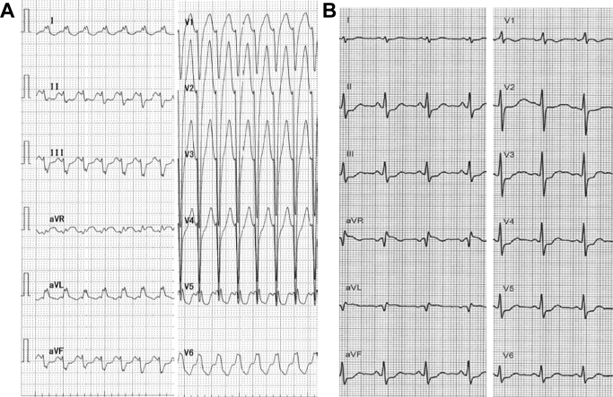

12-Lead Electrocardiogram Electrocardiogram on arrival (A) and after sinus rhythm restoration by adenosine triphosphate infusion (B).
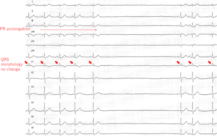
Effects of ATP Injection on Electrocardiogram During Sinus Rhythm The arrows point at QRS morphology, which was unchanged. ATP = adenosine triphosphate.
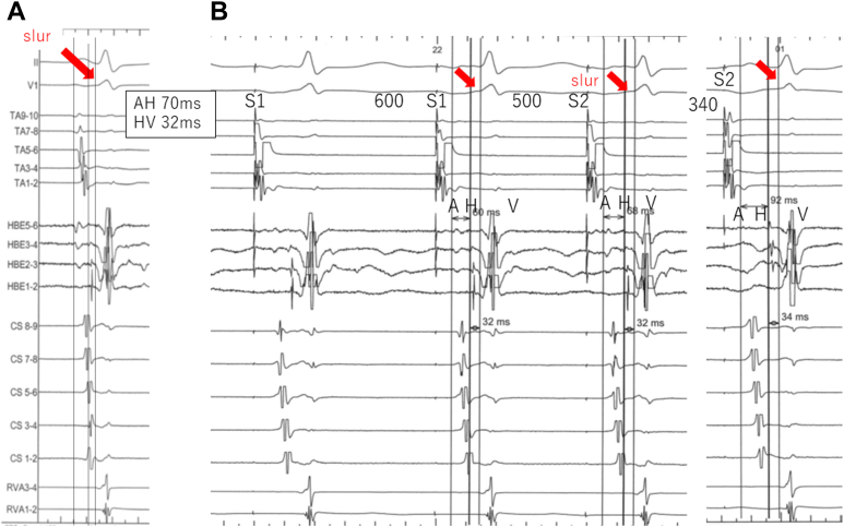
The Diagnosis of a Fasciculoventricular Accessory Pathway Intracardiac electrograms during sinus rhythm (A) and atrial programmed stimulation (B). The atrio-His (AH) interval prolong as the S1-S2 interval is shortened to 340 milliseconds with no change in the slur (arrows) or in the His-ventricular (HV) interval. A fasciculoventricular accessory pathway is diagnosed.
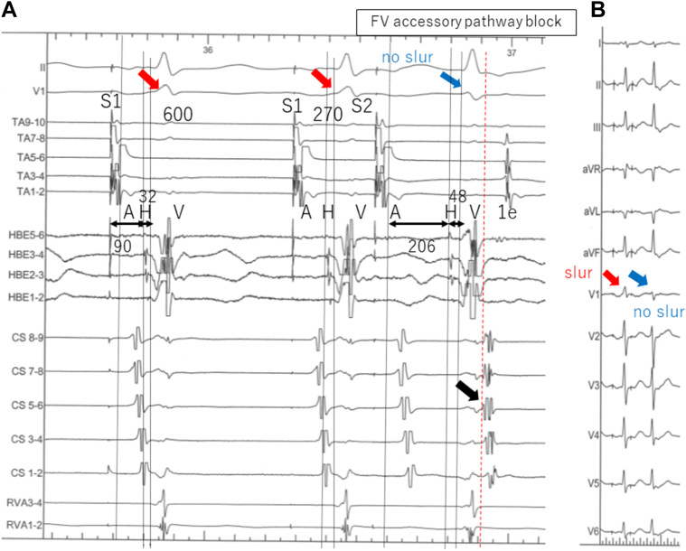
Atrial Programmed Stimulation Intracardiac electrograms (A) and 12-lead electrocardiogram (B) during atrial programmed stimulation. When the S1-S2 interval is shortened to 270 milliseconds, in addition to the atrio-His interval prolongation, the His-ventricular interval is prolonged by 16 milliseconds and the slur wave disappears. This is accompanied by an echo beat (1e) with earliest activation in lead CS 5-6 (black arrow). Fasciculoventricular (FV) accessory pathway block is diagnosed. Red arrows point at the slur and blue arrows at QRS complexes without the slur.
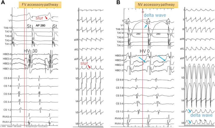
Atrial Constant Stimulation Intracardiac electrograms and 12-lead electrocardiogram with fasciculoventricular (FV) accessory pathway (A) and right-sided nodoventricular (NV) accessory pathway (B) conduction during atrial constant stimulation of 280 milliseconds. Red arrows in panel A point at the slur. Blue arrows in B point at the local ventricular electrogram in HBE3-4, which fuses with His potential, resulting in a local His-ventricular (HV) interval of 0 milliseconds and delta waves in leads V5 and V6.
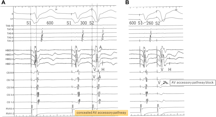
Intracardiac Electrograms During Ventricular Programmed Extrastimulation (A) Ventriculoatrial conduction is eccentric without decrements. (B) The atrioventricular (AV) accessory pathway is blocked, and His-atrial block also occurs via AV nodal conduction while drive train (S1) is 600 milliseconds and S1-S2 is 260 milliseconds.
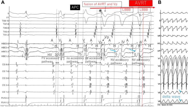
Initiation of Orthodromic AVRT With LBBB Configuration (A) After an atrial premature contraction (APC) with narrow QRS complex during ventricular pacing, a tachycardia with retrograde AV accessory pathway conduction starts. The second beat (asterisk) is a fusion of QRS without any accessory pathway tracts (HV interval of 70 milliseconds) and ventricular pacing, when suddenly QRS transitions to a left bundle branch block (LBBB) configuration accompanied by a change in local HV interval to 0 milliseconds in HBE2-3 (blue arrows). (B) On the surface electrocardiogram, blue arrows point at delta waves in leads V5 and V6. AVRT = atrioventricular re-entrant tachycardia; Vp = ventricular pacing; other abbreviations as in Figures 3, 5, and 6.
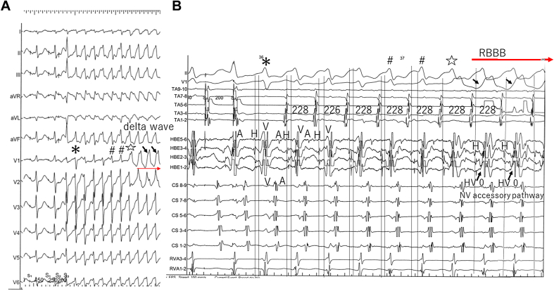
Induction of Orthodromic AVRT With RBBB Configuration Surface 12-lead electrocardiogram (A) and intracardiac electrograms (B) during induction of orthodromic AVRT with right bundle branch block (RBBB) configuration. During programmed atrial stimulation with 2 extrastimuli (S1-S1 = 450 milliseconds, S1-S2 = 250 milliseconds, S2-S3 = 200 milliseconds), tachycardia with retrograde AV accessory pathway conduction starts, with the initial beat a narrow QRS complex without FV accessory pathway conduction (asterisk). A series of various QRS configurations is subsequently followed by a switch to RBBB configuration, accompanied by change in local HV interval to 0 milliseconds and the initial deflection of local ventricular electrogram from negative to positive in HBE1-2. QRS complexes with the same signs (∗, #, ⋆, and Δ) are identical in A and B. Black arrows point at delta waves in V1 and the local ventricular electrogram in HBE1-2.Abbreviations as in Figures 3, 5, 6, and 7.
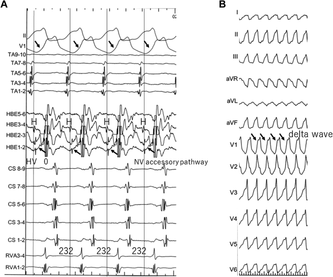
Orthodromic AVRT With RBBB Configuration Intracardiac electrograms (A) and 12-lead electrocardiogram (B) during orthodromic AVRT with RBBB configuration. After the QRS morphology of the tachycardia stabilizes to RBBB configuration, the tachycardia cycle also stabilizes (to 232 milliseconds). Black arrows in A point at the local ventricular electrogram in HBE1-2, which fuses with His potential, resulting in the local HV interval of 0 milliseconds. Note that the QRS has a delta wave (black arrows). Abbreviations as in Figures 5, 7, and 8.
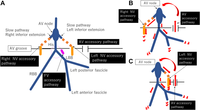
Schematic Diagram Schematic diagram of the putative accessory pathways in this patient (A), and the circuits of AVRT when displaying LBBB configuration (B) and RBBB configuration (C). The normal cardiac conduction system is described in blue in A; both NV accessory pathways are described in orange, and the FV accessory pathway in pink. The putative parts of the accessory pathways are shown with a dotted line. Abbreviations as in Figures 5 to 8.
References
-
- Nazer B., Walters T.E., Dewland T.A., et al. Variable presentations and ablation sites for manifest nodoventricular/nodofascicular fibers. Circ Arrhythm Electrophysiol. 2019;12 - PubMed
-
- Hoffmayer K.S., Lee B.K., Vedantham V., et al. Variable clinical features and ablation of manifest nodofascicular/ventricular pathways. Circ Arrhythm Electrophysiol. 2015;8:117–127. - PubMed
-
- Cardona-Guarache R., Han F.T., Nguyen D.T., et al. Ablation of supraventricular tachycardias from concealed left-sided nodoventricular and nodofascicular accessory pathways. Circ Arrhythm Electrophysiol. 2020;13 - PubMed
-
- Ho S.Y. Anatomy of the atrioventricular junction, atrioventricular grooves, and accessory pathways. Card Electrophysiol Clin. 2020;12:437–445. - PubMed
-
- Inoue S., Becker A.E. Posterior extensions of the human compact atrioventricular node: a neglected anatomic feature of potential clinical significance. Circulation. 1998;97:188–193. - PubMed
Publication types
LinkOut - more resources
Full Text Sources
