. 2024 Apr;19(4):514-523.
doi: 10.1038/s41565-023-01570-5. Epub 2024 Jan 11.

Nanoporous graphene-based thin-film microelectrodes for in vivo high-resolution neural recording and stimulation

Affiliations

Nanoporous graphene-based thin-film microelectrodes for in vivo high-resolution neural recording and stimulation

Damià Viana et al. Nat Nanotechnol. 2024 Apr.

Abstract

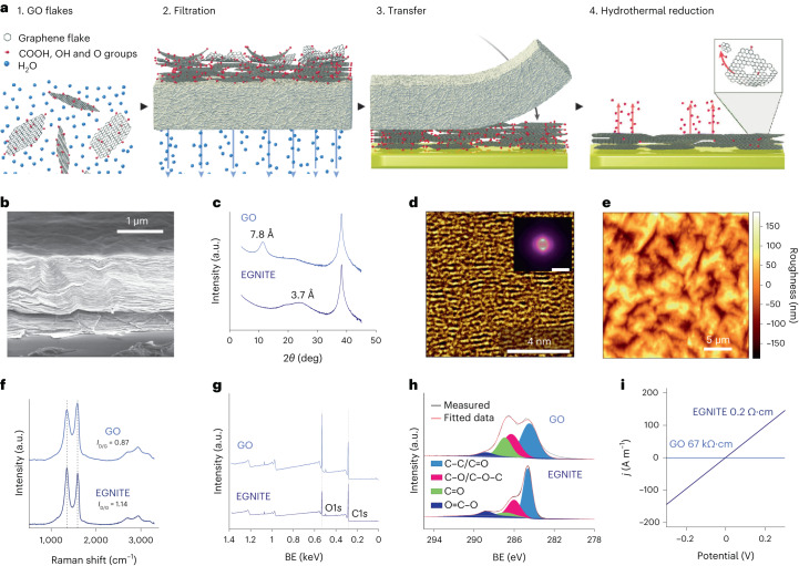
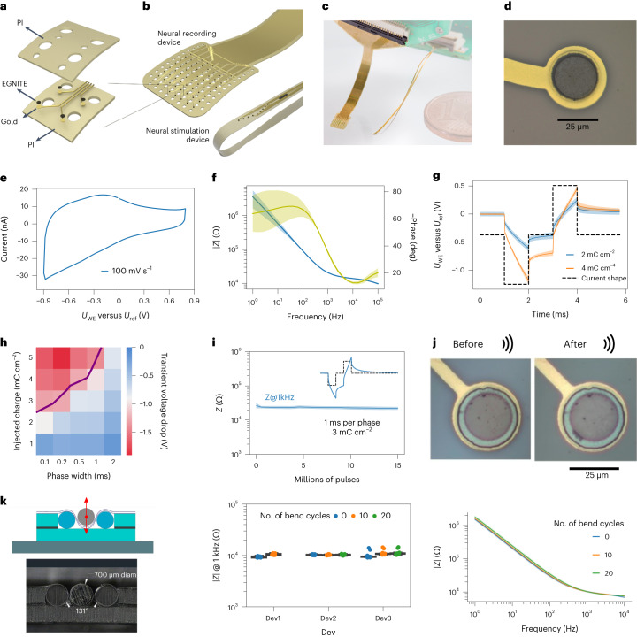
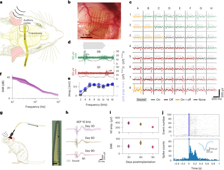
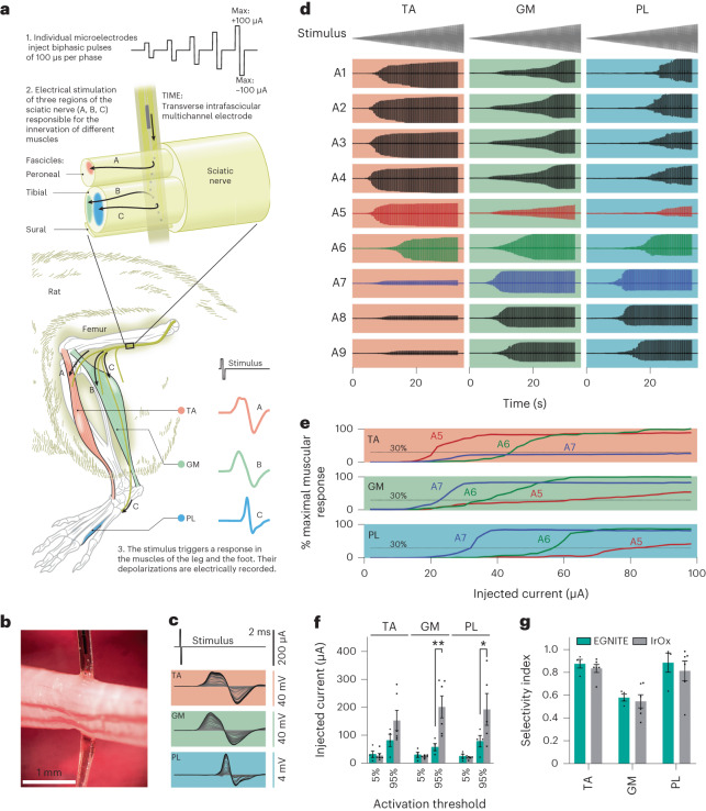
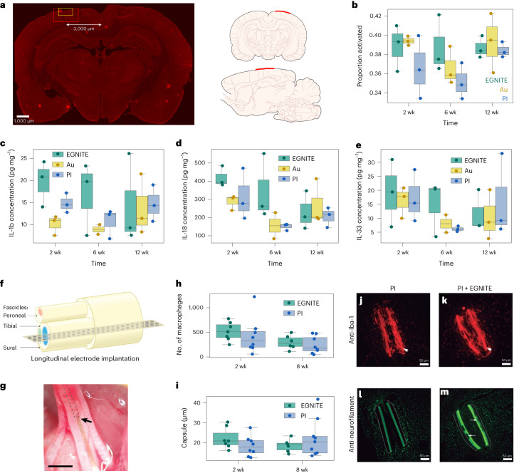
One of the critical factors determining the performance of neural interfaces is the electrode material used to establish electrical communication with the neural tissue, which needs to meet strict electrical, electrochemical, mechanical, biological and microfabrication compatibility requirements. This work presents a nanoporous graphene-based thin-film technology and its engineering to form flexible neural interfaces. The developed technology allows the fabrication of small microelectrodes (25 µm diameter) while achieving low impedance (∼25 kΩ) and high charge injection (3-5 mC cm-2). In vivo brain recording performance assessed in rodents reveals high-fidelity recordings (signal-to-noise ratio >10 dB for local field potentials), while stimulation performance assessed with an intrafascicular implant demonstrates low current thresholds (<100 µA) and high selectivity (>0.8) for activating subsets of axons within the rat sciatic nerve innervating tibialis anterior and plantar interosseous muscles. Furthermore, the tissue biocompatibility of the devices was validated by chronic epicortical (12 week) and intraneural (8 week) implantation. This work describes a graphene-based thin-film microelectrode technology and demonstrates its potential for high-precision and high-resolution neural interfacing.


Conflict of interest statement

D.V., A.G.B., K.K. and J.A.G. declare that they hold interest in INBRAIN Neuroelectronics which has licensed the technology described in this paper. All other authors declare no competing interests.

Figures

Fig. 1
Fig. 1. Preparation of nanoporous reduced GO thin films.
a, Preparation of the porous reduced GO thin-film EGNITE. This consists of filtering a GO solution through a porous membrane (1, 2), transferring the deposited film of stacked GO flakes onto a conductive substrate (3) and the hydrothermal reduction of the ensemble, which turns the film highly porous and conductive (4). b, SEM micrograph of a cross section of the material. c, X-ray diffraction of GO and EGNITE, revealing the characteristic peaks corresponding to the parallel stacking of the GO and reduced GO flakes. d, HRTEM false-colour cross-sectional view of EGNITE. Inset: corresponding power spectrum showing two symmetric diffuse spots, indicating the preferred stacking direction in the material and slight fluctuation of the flakes’ interplanar distance. Scale bar, 0.1 nm. e, AFM image revealing roughness of the upper surface of the EGNITE film. f, Raman spectra of the GO and EGNITE. The ratio between D and G peaks increases after the hydrothermal treatment. g, XPS full spectrum. BE, binding energy. h, C1s peak of (top) GO and (bottom) EGNITE. The decrease of the oxygen signal indicates the reduction of the GO film. i, Conductivity of the GO and EGNITE films.
Fig. 2
Fig. 2. Microfabrication, electrochemical and structural assessment of microelectrodes based on EGNITE.
a, Layers involved in the microfabrication of flexible arrays of microelectrodes of EGNITE. b, Designs of epicortical and intraneural arrays used in this work. c, Photograph of flexible implants based on EGNITE. d, Detailed micrograph of an EGNITE microelectrode of 25 µm diameter. e, Representative CV at 100 mV s−1 of an EGNITE microelectrode. f, EIS of EGNITE microelectrodes, showing the module (blue line) and phase (yellow line) of the impedance versus frequency. n = 18 electrodes. g, Voltage response to current-controlled biphasic pulses of 1 ms per phase (dashed lined) applied through EGNITE electrodes, corresponding to charge injection values of 2 and 4 mC cm2. h, Map of the cathodic capacitive voltage excursion occurring at the interface between EGNITE microelectrodes and the electrolyte during the injection of current pulses at different levels of injected charge and pulse widths. i, Evolution of impedance at 1 kHz throughout continuous stimulation with 15 µA (3 mC cm2) biphasic pulses of 1 ms per phase. gi, n = 3 electrodes. j, Images of EGNITE electrodes fabricated in a PI device before and after 15 min of ultrasonication. k, Left: schematic and cross section of the bending set-up, indicating the pressure of a cylindrical bar of 700 µm diameter producing bending angles of 131°. Centre: impedance magnitude at 1 kHz for three different devices, each with 18 microelectrodes, measured before and after 10 and 20 bending cycles. Right: impedance spectrum for a device before and after 10 and 20 cycles of bending. Line represents the mean and shading the s.d. In f,g,i,k, data are mean (solid lines) ± s.d. (shaded area). In boxplots, the median, quartile box and minimum and maximum values (excluding outliers) are presented.
Fig. 3
Fig. 3. EGNITE-based μECoG arrays map with high spatiotemporal fidelity local field potentials and MUAs.
a, Schematic diagram of the acute experiment using an EGNITE µECoG flexible array to record epicortical neural activity of a rat. Evoked activity was induced by pure tone stimuli. b, EGNITE µECoG array on the auditory cortex of a rat. c, Mapping of the evoked neural activity in response to 16 kHz stimuli, depicting a single event across all 64 EGNITE microelectrodes. Depending on the region, onset (green), offset (red), both (yellow) or no onset/offset (dark grey) responses are recorded. d, Response of regions G1 (onset, green) and D8 (offset, red) and HPF at 200 Hz to reveal high-frequency MUA activity (green and red), confirmed by a simultaneous increase in the r.m.s. value of the signal (grey). e, Maximum amplitude of the responses to sound stimuli at 2, 4, 6, 8, 10, 12, 14 and 16 kHz for the LFP HPF signal at 10 Hz (grey lines) and the averaged r.m.s. value of the signals above 200 Hz (r.m.s. MUA, blue lines), n = 15 stimuli. f, SNR (dB) calculated from the ratio of the in vivo and the post-mortem signals. Data are mean (solid line) ± s.d. (shaded area). g, Left: schematic diagram of intracortical flexible array configuration to record neural activity about 1.7 mm deep into the prefrontal cortex with EGNITE electrodes. Right: photograph of the microelectrode array tip. h, Averaged AEPs recorded 30, 60 and 90 days postimplantation. Data are mean (solid line) ± s.d. (shaded areas), n = 30 events. i, Top: peak N1 voltage change throughout 90 day intracortical device implantation. Bottom: SNR of the events. Data are mean ± s.d., n = 30 events. Data (single animal) recorded from same electrode are shown at days 30, 60 and 90. j, At day 30 postimplantation, there is robust spiking activity after the tone. Raster plot (top), peristimulus time histogram (bottom) and mean waveform (inset) of an individual neuron for 100 tone stimuli.
Fig. 4
Fig. 4. In vivo neural stimulation of peripheral nerve.
a, Schematic diagram of the acute stimulation experiments. A TIME array is implanted in the sciatic nerve of the rat crossing the peroneal and the tibial fascicles. The axons innervating the TA muscle are in the peroneal fascicle, whereas the axons innervating the GM and PL muscles are located in the tibial fascicle. Biphasic pulses of 100 µs per phase and increasing intensity were injected independently at the nine microelectrodes (diameter, 25 µm) present in the device. The local electrical stimulation can depolarize the nerve fibres in its vicinity and trigger the electrical activity of the muscles, which is recorded with needle electrodes. b, Optical micrograph of the implanted TIME device in the sciatic nerve. c, CMAPs recorded from TA, GM and PL muscles in response to increasing levels of injected current pulses applied to one of the electrodes. d, Recorded CMAPs in TA, GM and PL muscles in response to trains of biphasic current pulses of increasing amplitude applied to nine microelectrodes of the array (A1–A9). e, Normalized CMAP of TA, GM and PL muscles in response to pulses injected to microelectrodes A5–A7 from the implanted TIME. f, Comparative plot of the injected current needed to elicit 5% and 95% of the maximum CMAP using microelectrodes of EGNITE (cyan, n = 4) and of iridium oxide (grey, n = 6). *P = 0.039, **P = 0.0032 (two-way ANOVA followed by Bonferroni post hoc test for differences between groups). g, Comparative plot of the selectivity index at the minimal functionally relevant muscular stimulation for the same data as in f. In f,g, data are mean ± s.e.m.
Fig. 5
Fig. 5. Biocompatibility of EGNITE technology in brain and sciatic nerve.
Cortical tissue response. a, Left: representative brain section, postimplantation (left hemisphere) immunohistochemically stained for Iba-1. White arrow indicates the area of interest that was set at 3,000 µm from midline, based on average centre of device implantation. Red box: 8× magnification area used for microglial phenotype morphological analysis. Yellow box: 20× magnification area used to take representative images for the Iba-1 analysis in Supplementary Fig. 14. Right: EGNITE device implant location shown by the red line on coronal and sagittal rat brain sections. b, Iba-1 signal based on image processing of immunohistochemical sections. ce, ELISA-based quantification of anti-inflammatory and proinflammatory cytokine levels (IL-1b (c), IL-18 (d), IL-33 (e)) normalized to total protein content (mg ml−1) of the tissue samples in direct contact with the EGNITE microelectrodes for 2, 6 and 12 weeks following their epicortical implantation. n = 3 for each device material. Peripheral nerve tissue response. f, Schematic of the intraneural biocompatibility experiment. A PI device with and without EGNITE is implanted in the tibial branch of the sciatic nerve of rats. g, Optical micrograph of the longitudinally implanted device in the rat sciatic nerve. Scale bar, 1 mm. The arrow indicates the insertion point, and the dashed lines indicate the placement of the intraneural device within the tibial fascicle. h, Number of inflammatory Iba-1-positive cells in the tibial nerve after 2 and 8 weeks of longitudinal implantation. i, Tissue capsule thickness formed around the implanted device. Boxplots, n = 7 for each device material. jm, Representative images of transverse sections of a tibial nerve at 8 weeks after implantation of biocompatibility devices, made of PI alone (j,l) or PI with EGNITE (k,m), stained for inflammatory cells (antibody against Iba-1, j,k) and for axons (antibody against neurofilament 200, l,m). The arrowhead points to the transverse sections of the PI strips that were longitudinally inserted in the nerve. The arrows point to a site with EGNITE in the PI strip in m. The tissue capsule is delineated as dotted lines in l and m. Scale bar, 50 µm. The number of samples for the histological analyses was n = 6–7 per condition and time postimplantation. In boxplots, the median, quartile box and minimum and maximum values (excluding outliers) are presented.

References

    1. Hariz M. Twenty-five years of deep brain stimulation: celebrations and apprehensions. Mov. Disord. 2012;27:930–933. - PubMed
    1. Macherey O, Carlyon RP. Cochlear implants. Curr. Biol. 2014;24:R878–R884. - PubMed
    1. Raspopovic S, et al. Restoring natural sensory feedback in real-time bidirectional hand prostheses. Sci. Transl. Med. 2014;6:222ra19–222ra19. - PubMed
    1. Dhillon, G. S. & Horch, K. W. Neuroprosthetics: Theory And Practice (World Scientific, 2004).
    1. Chae, M. S., Yang, Z. & Liu, W. Microelectronics of recording, stimulation, and wireless telemetry for neuroprosthetics: design and optimization. in Implantable Neural Prostheses 2:Techniques and Engineering Approaches (eds Zhou, D. & Greenbaum, E.) 253–330 (Springer, 2010).