Differences in Trochlear Morphology of a New Femoral Component Designed for Kinematic Alignment from a Mechanical Alignment Design
- PMID: 38247939
- PMCID: PMC10812931
- DOI: 10.3390/bioengineering11010062
Differences in Trochlear Morphology of a New Femoral Component Designed for Kinematic Alignment from a Mechanical Alignment Design
Abstract
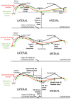
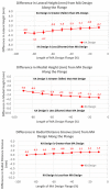
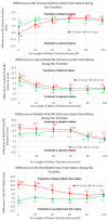
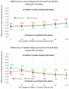
Because kinematic alignment (KA) aligns femoral components in greater valgus and with less external rotation than mechanical alignment (MA), the trochlear groove of an MA design used in KA is medialized, which can lead to complications. Hence, a KA design has emerged. In this study, our primary objective was to quantify differences in trochlear morphology between the KA design and the MA design from which the KA design evolved. The KA and MA designs were aligned in KA on ten 3D femur-cartilage models. Dependent variables describing the morphology of the trochlea along the anterior flange, which extends proximal to the native trochlea, and along the arc length of the native trochlea, were determined, as was flange coverage. Along the anterior flange, the KA groove was significantly lateral proximally by 10 mm and was significantly wider proximally by 5 mm compared to the MA design (p < 0.0001). Along the arc length of the native trochlea, the KA groove was significantly lateral to the MA design by 4.3 mm proximally (p ≤ 0.0001) and was significantly wider proximally by 19 mm than the MA design. The KA design reduced lateral under-coverage of the flange from 4 mm to 2 mm (p < 0.0001). The KA design potentially mitigates risk of patellofemoral complications by lateralizing and widening the groove to avoid medializing the patella for wide variations in the lateral distal femoral angle, and by widening the flange laterally to reduce under-coverage. This information enables clinicians to make informed decisions regarding use of the KA design.
Keywords: patellar tracking; patellofemoral complications; patellofemoral instability; patellofemoral joint; total knee arthroplasty; total knee replacement.
Conflict of interest statement
MLH receives research support from Medacta USA, Inc. and is on the Editorial Board of the
Figures


Similar articles
-
Kinematic alignment more closely restores the groove location and the sulcus angle of the native trochlea than mechanical alignment: implications for prosthetic design.Knee Surg Sports Traumatol Arthrosc. 2019 May;27(5):1504-1513. doi: 10.1007/s00167-018-5220-z. Epub 2018 Oct 24. Knee Surg Sports Traumatol Arthrosc. 2019. PMID: 30357423
-
The Trochlear Groove of a Femoral Component Designed for Kinematic Alignment Is Lateral to the Quadriceps Line of Force and Better Laterally Covers the Anterior Femoral Resection Than a Mechanical Alignment Design.J Pers Med. 2022 Oct 16;12(10):1724. doi: 10.3390/jpm12101724. J Pers Med. 2022. PMID: 36294863 Free PMC article.
-
Differences in Trochlear Morphology from Native Using a Femoral Component Interfaced with an Anatomical Patellar Prosthesis in Kinematic Alignment and Mechanical Alignment.J Knee Surg. 2022 May;35(6):625-633. doi: 10.1055/s-0040-1716413. Epub 2020 Sep 14. J Knee Surg. 2022. PMID: 32927493
-
Kinematic alignment adequately restores trochlear anatomy, patellar kinematics and kinetics in total knee arthroplasty: A systematic review.Knee Surg Sports Traumatol Arthrosc. 2025 Feb;33(2):606-620. doi: 10.1002/ksa.12401. Epub 2024 Aug 5. Knee Surg Sports Traumatol Arthrosc. 2025. PMID: 39101252
-
Surgical technique in patellofemoral arthroplasty.Orthop Traumatol Surg Res. 2019 Feb;105(1S):S165-S176. doi: 10.1016/j.otsr.2018.05.020. Epub 2019 Jan 8. Orthop Traumatol Surg Res. 2019. PMID: 30635231 Review.
Cited by
-
Medial Deviation of a 6° Prosthetic Trochlear Groove After Kinematically Aligned Total Knee Arthroplasty Occurs in Four Types of Coronal Plane Alignment of the Knee (CPAK) and Decreases the Forgotten Joint Score.Arthroplast Today. 2024 Dec 12;30:101569. doi: 10.1016/j.artd.2024.101569. eCollection 2024 Dec. Arthroplast Today. 2024. PMID: 39759179 Free PMC article.
-
The Orientation of the Prosthetic Trochlear Angle Is Predictable in Kinematically Aligned Total Knee Arthroplasty.J Pers Med. 2025 Jan 28;15(2):52. doi: 10.3390/jpm15020052. J Pers Med. 2025. PMID: 39997329 Free PMC article.
-
Does Alignment Technique in Medially Stabilized Total Knee Arthroplasty Affect the Patellofemoral Joint Biomechanics and Patient-reported Outcomes at 1 Year? A Prospective Registry-based Cohort Study.Arthroplast Today. 2025 Jun 26;34:101750. doi: 10.1016/j.artd.2025.101750. eCollection 2025 Aug. Arthroplast Today. 2025. PMID: 40641830 Free PMC article.
References
-
- Conditt M.A., Noble P.C., Allen B., Shen M., Parsley B.S., Mathis K.B. Surface damage of patellar components used in total knee arthroplasty. J. Bone Joint Surg. 2005;87:1265–1271. - PubMed
Grants and funding
LinkOut - more resources
Full Text Sources

