. 2024 Jan 12;11(1):75.
doi: 10.3390/bioengineering11010075.

Feasibility of a Shape-Memory-Alloy-Actuator System for Modular Acetabular Cups

Affiliations

Feasibility of a Shape-Memory-Alloy-Actuator System for Modular Acetabular Cups

Christian Rotsch et al. Bioengineering (Basel). .

Abstract

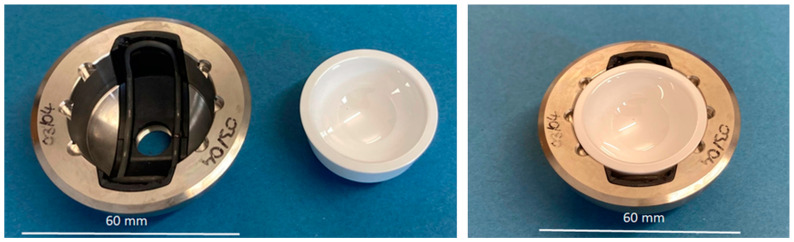
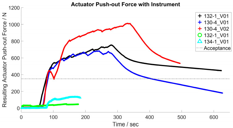
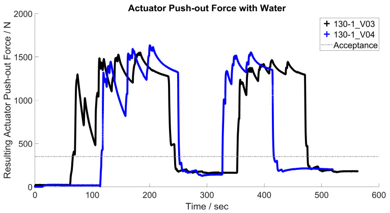
Hip implants have a modular structure which enables patient-specific adaptation but also revision of worn or damaged friction partners without compromising the implant-bone connection. To reduce complications during the extraction of ceramic inlays, this work presents a new approach of a shape-memory-alloy-actuator which enables the loosening of ceramic inlays from acetabular hip cups without ceramic chipping or damaging the metal cup. This technical in vitro study exam-ines two principles of heating currents and hot water for thermal activation of the shape-memory-alloy-actuator to generate a force between the metal cup and the ceramic inlay. Mechanical tests concerning push-in and push-out forces, deformation of the acetabular cup according to international test standards, and force generated by the actuator were generated to prove the feasibility of this new approach to ceramic inlay revision. The required disassembly force for a modular acetabular device achieved an average value of 602 N after static and 713 N after cyclic loading. The actuator can provide a push-out force up to 1951 N. In addition, it is shown that the necessary modifications to the implant modules for the implementation of the shape-memory-actuator-system do not result in any change in the mechanical properties compared to conventional systems.

Keywords: NiTi; Nitinol; SMA; acetabular cup; extraction; hip implant; implant; implant revision; shape memory alloy.


Conflict of interest statement

The authors declare no conflicts of interest. The funders had no role in the design of the study; in the collection, analyses, or interpretation of data; in the writing of the manuscript, or in the decision to publish the results.

Figures

Figure 1
Figure 1
Implant components, overview. 1—acetabular cup, 2—PEEK device, 3—SMA-actuator, 4—ceramic inlay.
Figure 2
Figure 2
Differential scanning calorimetry (DSC) of NiTiCuCr alloy for the determination of the phase transformation temperatures.
Figure 3
Figure 3
Implant components, assembly steps.
Figure 4
Figure 4
Activation of the SMA actuator with activation instrument (left) and with hot water (right).
Figure 5
Figure 5
Process chain of the SMA actuator.
Figure 6
Figure 6
Experimental setup, scheme.
Figure 7
Figure 7
Push-in (left), push-out (right) of ceramic inlay.
Figure 8
Figure 8
Test setup (left), implant components (right) for tests according to ASTM F 1875 [43] and ISO 7206-4:2010 [44]; 1—hip stem, 2—ceramic inlay, 3—ceramic ball, 4—acetabular cup, 5—SMA actuator, 6—PEEK device, 7—head adapter system.
Figure 9
Figure 9
Hip cup with spray patter (left), test setup hip cup deformation (right).
Figure 10
Figure 10
Ceramic inlay with undersize (left), instrument and implant components in the experimental setup (right).
Figure 11
Figure 11
Test setup for evaluating the actuator force with heated water: 1—hip cup with ceramic inlay, PEEK inlay with actuator, 2—syringe with hot/cold water, 3a—test setup for determining the resulting actuator force, 3b—display of the test machine, 4a—cup with water, 4b—temperature display for water, 5—display temperature sensor attached to the outside of the metal cup.
Figure 12
Figure 12
Push-in of ceramic inlays, force–distance diagram.
Figure 13
Figure 13
Push-out force, force–distance diagram.
Figure 14
Figure 14
Results push-out tests.
Figure 15
Figure 15
Deformation of metal cup; (left) modified geometry, (right) original geometry.
Figure 16
Figure 16
Forces generated by various actuators (130-1, 130-4; 132-1, 134-4) during push-out test, static state, heating by electrical current, acceptance criteria as reference.
Figure 17
Figure 17
Test procedure for evaluation of the actuators 130-1 and 130-4, heating by water, acceptance criteria as reference (selection).

Similar articles

Cited by

References

    1. Giuseppe M., Mattia B., Nadia B., Raffaele V., Pasquale R., Stefano D.A., Mattia S., Vincenzo D.S., Giulio M. Ceramic-on-ceramic versus ceramic-on-polyethylene in total hip arthroplasty: A comparative study at a minimum of 13 years follow-up. BMC Musculoskelet. Disord. 2022;22:1062. doi: 10.1186/s12891-021-04950-x. - DOI - PMC - PubMed
    1. El-Desouky I.I., Helal A.H., Mansour A.M.R. Ten-year survival of ceramic-on-ceramic total hip arthroplasty in patients younger than 60 years: A systematic review and meta-analysis. J. Orthop. Surg. Res. 2021;16:679. doi: 10.1186/s13018-021-02828-1. - DOI - PMC - PubMed
    1. Zhang X., Zhang Y., Jin Z. A review of the bio-tribology of medical devices. Friction. 2022;10:4–30. doi: 10.1007/s40544-021-0512-6. - DOI
    1. Morlock M.M., Bishop N., Kaddick C. Welche Hüftgelenkgleitpaarung für welchen Patienten? Tribologie der Zukunft. Der Orthopäde. 2011;40:1061–1067. doi: 10.1007/s00132-011-1849-8. - DOI - PubMed
    1. Rehmer A., Bishop N.E., Morlock M.M. Influence of assembly procedure and material combination on the strength of the taper connection at the head-neck junction of modular hip endoprostheses. Clin. Biomech. 2012;27:77–83. doi: 10.1016/j.clinbiomech.2011.08.002. - DOI - PubMed

LinkOut - more resources