

Study on the Cooling Performance of a Focused Ultrasonic Radiator for Electrical Heating Elements
- PMID: 38258235
- PMCID: PMC10820432
- DOI: 10.3390/mi15010116
Study on the Cooling Performance of a Focused Ultrasonic Radiator for Electrical Heating Elements
Abstract
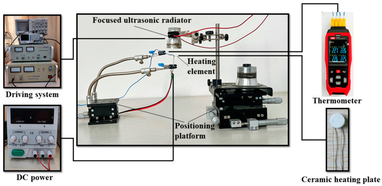
In this work, a focused ultrasonic radiator is proposed for cooling the electrical heating elements in the focal region, and its working characteristics are investigated. The analyses of the FEM computational and flow field visualization test results indicate that focused ultrasound can generate forced convective heat transfer by the acoustic streaming in the focal region, which can cool the heating elements effectively. Experiments show that when the input voltage is 30Vp-p and the ambient temperature is 25 °C, the focused ultrasonic radiator can cause the surface temperature of the heating element (high-temperature alumina ceramic heating plate with a diameter of 5 mm) in the focal region to drop from 100 °C to about 55 °C. When the diameter of the electrical heating element is changed from 5 mm to 30 mm, the cooling effect is similar in the focal region. Compared with a fan, the focused ultrasound radiator has a shorter cooling time and a more concentrated cooling area. The focused ultrasonic radiator proposed in this work is suitable for some special environments.
Keywords: acoustic streaming; electronic device; focused ultrasound; heat dissipation.
Conflict of interest statement
The authors declare no conflict of interest.
Figures


Similar articles
-
The effect of ultrasound irradiation on the convective heat transfer rate during immersion cooling of a stationary sphere.Ultrason Sonochem. 2012 Nov;19(6):1238-45. doi: 10.1016/j.ultsonch.2012.04.009. Epub 2012 Apr 27. Ultrason Sonochem. 2012. PMID: 22621749
-
Analysis of ultrasound-assisted convective heating/cooling process: Development and application of a Nusselt equation.Ultrason Sonochem. 2021 Jun;74:105575. doi: 10.1016/j.ultsonch.2021.105575. Epub 2021 Apr 25. Ultrason Sonochem. 2021. PMID: 33957370 Free PMC article.
-
Effect of acoustic field parameters on arc acoustic binding during ultrasonic wave-assisted arc welding.Ultrason Sonochem. 2016 Mar;29:476-84. doi: 10.1016/j.ultsonch.2015.11.001. Epub 2015 Nov 2. Ultrason Sonochem. 2016. PMID: 26558995
-
Experimental validation of a tractable numerical model for focused ultrasound heating in flow-through tissue phantoms.J Acoust Soc Am. 2004 Oct;116(4 Pt 1):2451-8. doi: 10.1121/1.1787124. J Acoust Soc Am. 2004. PMID: 15532675
-
Heat Transfer Enhancement by Hybrid Nano Additives-Graphene Nanoplatelets/Cellulose Nanocrystal for the Automobile Cooling System (Radiator).Nanomaterials (Basel). 2023 Feb 22;13(5):808. doi: 10.3390/nano13050808. Nanomaterials (Basel). 2023. PMID: 36903687 Free PMC article.
References
-
- Niazmand H., Renksizbulut M., Saeedi E. Developing Slip-Flow and Heat Transfer in Trapezoidal Microchannels. Int. J. Heat Mass Transf. 2008;51:6126–6135. doi: 10.1016/j.ijheatmasstransfer.2008.04.007. - DOI
-
- Wang H.T., Chen Z.H., Gao J.G. Influence of Geometric Parameters on Flow and Heat Transfer Performance of Micro-Channel Heat Sinks. Appl. Therm. Eng. 2016;107:870–879. doi: 10.1016/j.applthermaleng.2016.07.039. - DOI
-
- Chen C.H. Slip-Flow Heat Transfer in a Microchannel with Viscous Dissipation. Heat Mass Transf. 2006;42:853–860. doi: 10.1007/s00231-005-0052-z. - DOI
-
- Kumar V., Paraschivoiu M., Nigam K.D.P. Single-Phase Fluid Flow and Mixing in Microchannels. Chem. Eng. Sci. 2011;66:1329–1373. doi: 10.1016/j.ces.2010.08.016. - DOI
-
- Zhou W.N., Dong K.J., Sun Q., Luo W.M., Zhang B.B., Guan S.L., Wang G.W. Research Progress of the Liquid Cold Plate Cooling Technology for Server Electronic Chips: A Review. Int. J. Energy Res. 2022;46:11574–11595. doi: 10.1002/er.7979. - DOI
Grants and funding
LinkOut - more resources
Full Text Sources
