. 2024 Jun;71(6):1958-1968.
doi: 10.1109/TBME.2024.3357293. Epub 2024 May 20.

A Minimally Invasive Robotic Tissue Palpation Device

A Minimally Invasive Robotic Tissue Palpation Device

Mohammad Mir et al. IEEE Trans Biomed Eng. 2024 Jun.

Abstract

Objective: Robot-assisted minimally invasive surgery remains limited by the absence of haptic feedback, which surgeons routinely rely on to assess tissue stiffness. This limitation hinders surgeons' ability to identify and treat abnormal tissues, such as tumors, during robotic surgery.

Methods: To address this challenge, we developed a robotic tissue palpation device capable of rapidly and non-invasively quantifying the stiffness of soft tissues, allowing surgeons to make objective and data-driven decisions during minimally invasive procedures. We evaluated the effectiveness of our device by measuring the stiffness of phantoms as well as lung, heart, liver, and skin tissues obtained from both rats and swine.

Results: Results demonstrated that our device can accurately determine tissue stiffness and identify tumor mimics. Specifically, in swine lung, we determined elastic modulus (E) values of 9.1 ± 2.3, 16.8 ± 1.8, and 26.0 ± 3.6 kPa under different internal pressure of the lungs (PIP) of 2, 25, and 45 cmH2O, respectively. Using our device, we successfully located a 2-cm tumor mimic embedded at a depth of 5 mm in the lung subpleural region. Additionally, we measured E values of 33.0 ± 5.4, 19.2 ± 2.2, 33.5 ± 8.2, and 22.6 ± 6.0 kPa for swine heart, liver, abdominal skin, and muscle, respectively, which closely matched existing literature data.

Conclusion/significance: Results suggest that our robotic palpation device can be utilized during surgery, either as a stand-alone or additional tool integrated into existing robotic surgical systems, to enhance treatment outcomes by enabling accurate intraoperative identification of abnormal tissue.


Figures

Fig. 1.
Fig. 1.. Overview of the robotic tissue palpation device.
(A) A schematic showing the application of the device in measuring the stiffness of soft biological tissues. The device consists of a stiffness measurement probe positioned at the distal end of the deflectable catheter, an imaging fiber integrated into the device for visual guidance during device operation, and a motorized controller for manipulating the spatial orientation of the device during navigation and measurement. (B) A photograph of the robotic palpation device. Inset image: magnified front view of the measurement probe. (C) A schematic showing the components of the measurement probe: contact electrodes to confirm probe-tissue contact and maximum tissue deformation, force sensor to measure the force applied to the tissue during measurement, and imaging probe to provide visual information during device navigation and stiffness measurement. (D) A schematic showing i) undeformed tissue and (ii) and fully deformed tissue (LC: tissue deformation length) under applied force (FC). Maximum tissue deformation is confirmed when the flow of electrical current (I) is generated across the tissue between the contact electrodes integrated at the device distal end.
Fig. 2.
Fig. 2.. Multi-directional movements of the robotic tissue palpation device.
Multiplicity photographs illustrating (A) deflection, (B) titling, and (C) translational movements of the device accomplished through manipulation of individual motors integrated into the device. During device operation, these movements are collectively achieved by simultaneously controlling different motors to bring the distal end of the device to the tissue surface for the stiffness measurement.
Fig. 3.
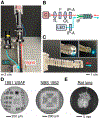
Fig. 3.. Custom-built micro-optical imaging module.
The imaging module for collecting visual information in bright-field and fluorescence imaging modes to guide the device for tissue assessment. (A) A photograph of the imaging module integrated into the palpation device and (B) light-path schematic of the imaging module. C: camera, LED: light-emitting diode, TL: tube lens, F: filter, OL: objective lens, IP-A: imaging probe adapter, IP: imaging probe. (C) A photograph showing the distal end of the palpation device incorporated with an optical fiber-based imaging probe. Inset images: excitation/illumination lights being emitted through the distal end of the imaging probe. (D) 1951 USAF and NBS 1952 test targets imaged using the imaging module showing the resolution of 80 mm/line and 72 mm/line, respectively. (E) A photograph of an explanted rat lung taken using the imaging probe positioned approximately 5 cm away from the lung.
Fig. 4.
Fig. 4.. Force sensor circuit construction and calibration.
(A) A photograph illustrating the experimental setup used to calibrate the thin film-based force sensor (GD03–10N, UNEO) used to construct the palpation device. Known magnitudes of compression force were applied directly to the force sensor incorporated underneath the hemispheric indentation head using a commercial force meter (M5–2 force gauge). Changes in the voltage were recorded to calibrate the force sensor. (B) A schematic of the electrical circuit to construct and calibrate the force sensor against different resistor incorporated (R: 1, 10, or 100 kΩ). (C) Voltage values measured from the force sensor against the compression force applied during the measurement. The circuit incorporated with a 100-kΩ resistor showed greater sensitivity at the force range of 0–0.5 N, as the changes in the voltage against the compression force was more drastic. This led to the use of a 100-kΩ resistor to construct the palpation device for the stiffness measurements conducted using soft phantoms and tissue in this study. F: force, R: reference resistor, RS: the resistance between force sensor conductive layers, GND: ground, VS: supply voltage.
Fig. 5.
Fig. 5.. Stiffness evaluation of gelatin-based tissue phantoms.
(A) Photographs showing: i) no contact and ii) full contact established between the tissue phantom and contact electrodes. In this configuration, a predefined deformation of a phantom or tissue is confirmed when an electrical current flows between the two contract electrodes, indicating the circuit has been closed due to the full contact between the electrodes with phantom or tissue. (B) A plot showing the force recorded over time as phantoms made of 10% v/w gelatin were being compressed using the device (rate of deformation: 5 mm/min). Region a: The probe approaching the phantom surface for measurement. Region b: The probe making a contact with the phantom and deforming it up to 2 mm (LC = 2 mm), which is equivalent to the height of the hemispherical compression head. Region c: No further compression induced due to full contact between the electrodes and phantom. Region d: The probe being retracted following the measurement. Region e: Complete detachment of the probe from the phantom as no force was being recorded. (C) Voltage (VE) recorded via the contact electrodes during the experiment. Maximum deformation (i.e., Region c) was confirmed when the electrical circuit is closed, which was indicated by 3.2 volts of VE measured. (D) A schematic showing the deformation of tissue sample (LC: deformation length) under applied force (FC) and the equation formulated to calculate the elastic modulus (E). r: radius of sensor indentation head, ν: Poisson ratio. (E) Demonstration of elastic modulus (E) measurements using phantom blocks (n = 6, gelatin concentration: 10%) with different thicknesses (2.5–20 mm) that were placed on a rigid acrylic substrate (E: ~3.1 GPa). As the phantom thickness increased, the measured E values decreased due to reduced effects of the substrate located underneath the phantom samples (**p-value < 0.01. ***p-value < 0.001. ns: not significant).
Fig. 6.
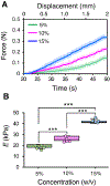
Fig. 6.. Stiffness evaluation of gelatin-based tissue phantoms with varying gelatin concentrations using the palpation device.
(A) Magnitude of the force measured continuously as the phantoms were compressed at a compression rate of 5 mm/min. Shaded regions indicate standard deviations. The slope of the force-displacement curve increased with an increase in gelatin concentration. (B) Elastic moduli of the phantoms calculated using the maximum deformation and force recorded during the measurements. Higher gelatin concentration was correlated with a higher elastic modulus. For 5, 10, and 15% w/v gelatin phantoms, the measured elastic moduli were 18.3 ± 1.5, 25.7 ± 2.2, and 42.5 ± 1.6 kPa, respectively (***p-value < 0.001).
Fig. 7.
Fig. 7.. Stiffness measurements of tissue phantoms with spatially heterogenous stiffness for demonstration of tumor mimic detection.
(A) Images and drawing showing a cylindrical PDMS-based nodule mimic embedded in a soft hydrogel for demonstration of the nodule detection using our palpation device. The nodule mimic (diameter: 12 mm; thickness: 2.5 mm; elastic modulus: 233.3 ± 16 kPa) was labeled with near-infrared dye ICG and embedded at the center of a gelatin block (concentration: 10% w/v; length: 35 mm, width: 35 mm, thickness: 10 mm; elastic modulus: 25.7 ± 2.2 kPa). The nodule mimic was visualized in the gelatin block (red) with NIR imaging to show its location within the gelatin. (B) The tissue phantom was scanned using the palpation device with a 5-mm spatial resolution. In the image, each grid represents a spot for the stiffness measurement. (C) Two-dimensional (2D) stiffness map was obtained following discrete measurements across the phantom’s surface. While the elastic moduli (E) of peripheral regions varied between 23 and 27 kPa, the E values increased to 38–50 kPa at the central region where the nodule mimic was embedded, highlighting the ability of the palpation device to detect the nodule mimic.
Fig. 8.
Fig. 8.. Stiffness measurements of ex vivo swine lungs and nodule mimic detection.
(A) A photograph of the measurement setup. Inset image: magnified view of the measurement probe positioned near the lung surface. (B) Elastic moduli of porcine lungs at different peak inspiratory pressure (PIP, n = 5). The E values increased with PIP, confirming that the tension of the lung tissue increased with PIP. The measured E values were 9.1 ± 2.3, 16.8 ± 1.8, and 26.0 ± 3.6 for 2, 25, and 45 cmH2O of PIP, respectively (***p-value < 0.001). (C) Lung tumor model was created by embedding a rigid PDMS-based nodule mimic (diameter: 2 cm; thickness: 5 mm; E: 233.3 ± 16 kPa) at the depth of 5 mm in the subpleural regions. Bright-field and NIR fluorescent images of the lung lobe embedded with a nodule mimic were acquired. (D) A stiffness map of the lung cancer model showing increased stiffness near the region where tumor mimic was embedded (i.e., E: 28.3 kPa). Lower E value measured for the nodule mimic within the lung can be attributed to the presence of soft lung tissue surrounding the rigid nodule.
Fig. 9.
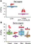
Fig. 9.. Stiffness measurement of rat and swine organs using the palpation device.
(A) Elastic moduli (E) of rat liver (n = 5) and lung (n = 5) were 2.6 ± 0.3 and 9.2 ± 0.5 kPa, respectively. (B) The measured E values of swine heart, liver, skin, and muscle were 33.0 ± 5.4, 19.2 ± 2.2, 33.5 ± 8.2, and 22.6 ± 6.0 kPa, respectively. The measured E values were consistent with data reported in the literature. PIP: Peak inspiratory pressure.

Similar articles

Cited by

References

    1. Peters BS et al., “Review of emerging surgical robotic technology,” Surg Endosc, vol. 32, no. 4, pp. 1636–1655, Apr, 2018. - PubMed
    1. Vitiello V et al., “Emerging Robotic Platforms for Minimally Invasive Surgery,” IEEE Reviews in Biomedical Engineering, vol. 6, pp. 111–126, 2013. - PubMed
    1. Omisore OM et al., “A Review on Flexible Robotic Systems for Minimally Invasive Surgery,” IEEE Transactions on Systems, Man, and Cybernetics: Systems, vol. 52, no. 1, pp. 631–644, 2022.
    1. Kim U et al., “A Surgical Palpation Probe With 6-Axis Force/Torque Sensing Capability for Minimally Invasive Surgery,” IEEE Transactions on Industrial Electronics, vol. 65, pp. 2755–2765, 2018.
    1. Ibrahim MK et al., “Robot-assisted for medical surgery: A literature review,” AIP Conference Proceedings, vol. 2591, no. 1, pp. 030008, 2023/03/29, 2023.

Publication types