Review
. 2024 Feb 6;18(5):3871-3915.
doi: 10.1021/acsnano.3c10033. Epub 2024 Jan 23.

Advances in Smart Photovoltaic Textiles

Affiliations
Review

Advances in Smart Photovoltaic Textiles

Iftikhar Ali et al. ACS Nano. .

Abstract

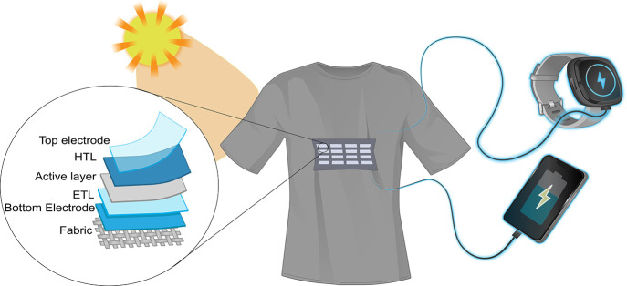
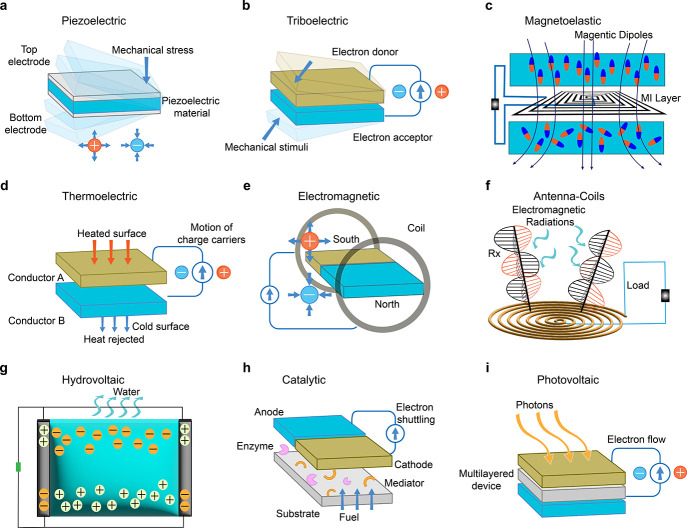
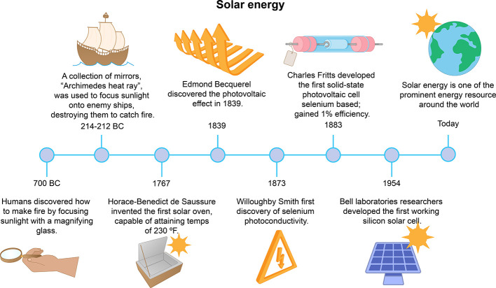
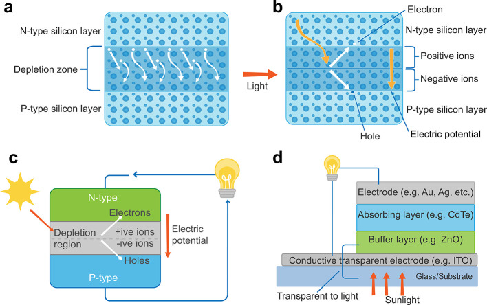
Energy harvesting textiles have emerged as a promising solution to sustainably power wearable electronics. Textile-based solar cells (SCs) interconnected with on-body electronics have emerged to meet such needs. These technologies are lightweight, flexible, and easy to transport while leveraging the abundant natural sunlight in an eco-friendly way. In this Review, we comprehensively explore the working mechanisms, diverse types, and advanced fabrication strategies of photovoltaic textiles. Furthermore, we provide a detailed analysis of the recent progress made in various types of photovoltaic textiles, emphasizing their electrochemical performance. The focal point of this review centers on smart photovoltaic textiles for wearable electronic applications. Finally, we offer insights and perspectives on potential solutions to overcome the existing limitations of textile-based photovoltaics to promote their industrial commercialization.

Keywords: electronic textiles; energy harvesting; green energy; photovoltaic textiles; smart textiles; solar cells; solar energy; wearable electronics.


Conflict of interest statement

The authors declare no competing financial interest.

Figures

Figure 1
Figure 1
Textile solar cells for powering wearable and portable devices.
Figure 2
Figure 2
Schematics of different energy harvesters’ working mechanisms. (a) Piezoelectric, (b) triboelectric, (c) magnetoelastic, (d) thermoelectric, (e) electromagnetic, (f) antenna-coils, (g) hydrovoltaic, (h) catalytic, and (i) photovoltaic.
Figure 3
Figure 3
Timeline of solar energy toward the development of a practical photovoltaic system.
Figure 4
Figure 4
Power generating mechanisms and structure of photovoltaic systems. General mechanism of photovoltaic process in SCs (a) without sunlight illumination and (b) with sunlight illumination. Schematics of (c) first-generation and (d) second-generation SCs.
Figure 5
Figure 5
Schematics of photovoltaic technologies in third-generation SCs. (a) Dye sensitized solar cell (DSSC), (b) perovskite solar cell (PSC), (c) organic solar cell (OSC), and (d) quantum dot solar cell (QDSC). (e) The energy transfer mechanism of the photovoltaic process in third-generation OSCs.
Figure 6
Figure 6
Schematics of photovoltaic textile architectures. 1D fiber-level SCs: (a) coaxial type and (b) twisting type; 2D textile-level SCs: (c) interlaced and (d) planar shape textile-based SCs.
Figure 7
Figure 7
General photovoltaic system measurement setup and performance metrics. (a) Measurement setup for a SC characterization; graphical representation of (b) maximum power output and (c) the fill factor.
Figure 8
Figure 8
Chemical structures of common electrode materials employed in photovoltaic systems. (a) Metals, (b) transparent conductive oxides (TCOs), (c) carbon-based, and (d) conductive polymers.
Figure 9
Figure 9
Chemical and crystal structures of commonly employed absorbing/active materials. (a) First-generation, (b) second-generation, and (c) third-generation SCs.
Figure 10
Figure 10
Chemical and crystal structures of commonly used (a) electron transport materials and (b) hole transport materials.
Figure 11
Figure 11
Spinning techniques for photovoltaic textile fabrication: (a) melt spinning, (b) electrospinning, and (c) wet spinning.
Figure 12
Figure 12
Coating techniques for photovoltaic textile fabrication. (a) Schematic of the spray coating system. Fully spray coated OSC device (b) SEM image and (c) the performance curve in both light and dark mode with an original photograph (inset) of the fabricated device. Reprinted with permission from ref (457). Copyright 2016 The Royal Society of Chemistry. (d) Schematic of a spin coating system. (e) A spin-coated wearable PSC device under sun simulator, while glowing an LED upon exposing to light and (f) the photograph of the spin-coated PSC device (inset) along with the corresponding IV curve under 1 sun condition. Reprinted with permission from ref (294). Copyright 2017 The Royal Society of Chemistry. (g) Schematic of dip coating process, (h) the photographs of the PSC device where the active layer was dip-coated and (i) the performance curves of the fabricated PSC with respect to different thicknesses of the active layer. Reproduced with permission from ref (462). Copyright 2014 Wiley-VCH Verlag GmbH and Co. KGaA, Weinheim.
Figure 13
Figure 13
Printing techniques for photovoltaic textiles fabrication. (a) Schematic of a screen printer and its different parts, (b) a photograph of screen printed DSSC-based on glass fabric and (c) the corresponding IV curve for two different devices with and without an interface layer. Reprinted in part with permission under a Creative Commons CC-BY License from ref (469). Copyright 2019 Springer Nature. (d) Schematic and different parts of inkjet printer. (e) Photographs of the inkjet-printed OSCs, where the shape OSC is fabricated in the shape of a Christmas tree. Reprinted in part with permission under a Creative Commons Attribution 3.0 Unported License from ref (473). Copyright 2015 The Royal Society of Chemistry. (f) The shape of an inkjet-printed sea turtle on an ITO Glass substrate. Reused with permission from ref (474). Copyright 2019 WILEY-VCH Verlag GmbH and Co. KGaA, Weinheim. These works demonstrate the capabilities of inkjet printing to be employed for a variety of fine patterns.
Figure 14
Figure 14
Assembly methods for photovoltaic textiles. (a) Schematic of a preprepared SCs stacking on a fabric, (b) flexible SCs wire interwoven, and (c) the IV curves before and after bending along with the photograph, powering an MP3 device under sunlight. Reproduced with permission from ref (478). Copyright 2014 WILEY-VCH Verlag GmbH and Co. KGaA, Weinheim. (d) Schematic of layer-by-layer process of a textile-based SC. (e) A photo of the layer-by-layer fabricated textile DSSC and (f) their IV curves in comparison to the standard device, respectively. Reproduced with permission from ref (484). Copyright 2017 Elsevier. (g) Schematic of SC’s yarns, interwoven with zoomed cross section and (h) A photograph of a SC yarn-based fabric. Reproduced with permission under a Creative Commons CC-BY License from ref (130). Copyright 2019 John Wiley and Sons. (i) The IV curves of a yarn-based SC in both yarn and textile shape, along with a photograph of the device (inset). Reproduced with permission from ref (485). Copyright 2015 WILEY-VCH Verlag GmbH and Co. KGaA, Weinheim.
Figure 15
Figure 15
Performance evaluation for DSSC-based photovoltaic textiles. (a) Schematic of a proposed 3D textile-based DSSC. (b) the electrical performance of the device: current density and specific power. (c) the relative efficiency with respect to the radius of curvature in centimeters along with a photograph of the fabricated textile-based DSSC. Reprinted in part with permission under a Creative Commons CC-BY License from ref (492). Copyright 2019 Springer Nature. (d) A schematic of a recently developed textile-based DSSC, (e) the current density and specific power of the fabricated device and (f) a photograph of the device in a bent shape along with the relative PCE with respect to the radius of curvature. Reprinted with permission from ref (493). Copyright 2014 Springer Nature. (g) A schematic of another recently investigated textile-based DSSC, (h) the current density curve of the device, and (i) a photograph of the fabricated device along with the normalized efficiency as per radius of curvature. Reprinted in part with permission under a Creative Commons CC-BY License from ref (218). Copyright 2016 Springer Nature.
Figure 16
Figure 16
Performance evaluation for PSC photovoltaic textiles. (a) Schematic of recently developed textile-based PSC along with (b) the SEM image of perovskite layer and (c) the current density of the fabricated textile PSC as well as a photograph of the fabricated device. Reproduced with permission from ref (458). Copyright 2018 Elsevier. (d) Schematic of a fiber-shaped PSC along with (e) the corresponding cross sectional SEM image of the device and (f) the electrical performance of the corresponding fiber shaped PSC and optical image (inset) of the device. Reproduced with permission from ref (496). Copyright 2016 The Royal Society of Chemistry. (g) Schematic of a fiber shape textile PSC, (h) corresponding SEM image with indication of different layers, and (i) the electrical performance curves. Reproduced with permission from ref (205). Copyright 2018 The Royal Society of Chemistry.
Figure 17
Figure 17
Performance evaluation for OSC photovoltaic textiles. (a) Schematic of a fabricated textile-based OSC, (b) a photograph of textile-based OSCs and (c) the IV curve for 100 bending cycles which is almost similar, demonstrating the flexibility of the fabricated device. Reproduced with permission from ref (131). Copyright 2019 American Chemical Society. (d) Schematic of a textile based OSC, (e) photograph of a device fixed on a shirt, showing high flexibility, and (f) the performance curve of the device in free stand mode on a perylene substrate. Reproduced with permission from ref (507). Copyright 2017 Springer Nature. (g) Schematic of fiber-shaped OSC, (h) a photograph of the fabricated fiber-shaped OSCs both before and after deformation, and (i) the current density curve along with an SEM image (inset). Reproduced with permission from ref (509). Copyright 2014 John Wiley and Sons.
Figure 18
Figure 18
Washability performance evaluation for photovoltaic textiles. (a) Photographs of a fabricated textile-based OSC device, (b) electrical performance curves after passing through different washing cycles and (c) the demonstration of the relative changes in performance with respect to washing cycles such as Voc, PCE. Reproduced with permission from ref (563). Copyright 2018 The Royal Society of Chemistry. (d) In these set of images, five solar-E-yarns woven into a textile are shown in their dry state, soaked with tap water, and immersed in tap water. (e) The normalized ISC with different hand and machine-washing cycles, and (f) the number of fully functional solar-E-yarns after 25 washing cycles. Reproduced with permission under a Creative Commons CC-BY License from ref (130). Copyright 2019 John Wiley and Sons.
Figure 19
Figure 19
Future perspectives of smart photovoltaic textiles.

Similar articles

Cited by

References

    1. Libanori A.; Chen G.; Zhao X.; Zhou Y.; Chen J. Smart textiles for personalized healthcare. Nat. Electron. 2022, 5 (3), 142–156. 10.1038/s41928-022-00723-z. - DOI
    1. Chen G.; Xiao X.; Zhao X.; Tat T.; Bick M.; Chen J. Electronic Textiles for Wearable Point-of-Care Systems. Chem. Rev. 2022, 122 (3), 3259–3291. 10.1021/acs.chemrev.1c00502. - DOI - PubMed
    1. Zhang Y.; Wang H.; Lu H.; Li S.; Zhang Y. Electronic fibers and textiles: Recent progress and perspective. iScience 2021, 24 (7), 10271610.1016/j.isci.2021.102716. - DOI - PMC - PubMed
    1. Zhao J.; Fu Y.; Xiao Y.; Dong Y.; Wang X.; Lin L. A naturally integrated smart textile for wearable electronics applications. Adv. Mater. Technol. 2020, 5 (1), 190078110.1002/admt.201900781. - DOI
    1. Uddin M. A.; Afroj S.; Hasan T.; Carr C.; Novoselov K. S.; Karim N. Environmental Impacts of Personal Protective Clothing Used to Combat COVID- 19. Adv. Sustain. Syst. 2022, 6 (1), 210017610.1002/adsu.202100176. - DOI - PMC - PubMed