Review
. 2023 Dec 21;10(1):4.
doi: 10.3390/gels10010004.

Hybrid and Single-Component Flexible Aerogels for Biomedical Applications: A Review

Affiliations
Review

Hybrid and Single-Component Flexible Aerogels for Biomedical Applications: A Review

Mateusz Fijalkowski et al. Gels. .

Abstract

The inherent disadvantages of traditional non-flexible aerogels, such as high fragility and moisture sensitivity, severely restrict their applications. To address these issues and make the aerogels efficient, especially for advanced medical applications, different techniques have been used to incorporate flexibility in aerogel materials. In recent years, a great boom in flexible aerogels has been observed, which has enabled them to be used in high-tech biomedical applications. The current study comprises a comprehensive review of the preparation techniques of pure polymeric-based hybrid and single-component aerogels and their use in biomedical applications. The biomedical applications of these hybrid aerogels will also be reviewed and discussed, where the flexible polymeric components in the aerogels provide the main contribution. The combination of highly controlled porosity, large internal surfaces, flexibility, and the ability to conform into 3D interconnected structures support versatile properties, which are required for numerous potential medical applications such as tissue engineering; drug delivery reservoir systems; biomedical implants like heart stents, pacemakers, and artificial heart valves; disease diagnosis; and the development of antibacterial materials. The present review also explores the different mechanical, chemical, and physical properties in numerical values, which are most wanted for the fabrication of different materials used in the biomedical fields.

Keywords: biocompatible aerogels; flexible hybrid aerogels; flexible scaffolds; flexible single-component aerogels; mechanical properties; sustained drug delivery; tissue engineering.


Conflict of interest statement

The authors declare no conflicts of interest.

Figures

Figure 1
Figure 1
Percentage of aerogels depending on chemical components; data compiled from Web of Science spanning from 2010 to May 2020. Reprint with permission from [Jingyun Jing] (Recent Advances in the Synthesis and Application of Three-Dimensional Graphene-Based Aerogels); published by MDPI (2022) [16].
Figure 2
Figure 2
A Schematic diagram illustrating the process for creating GO/PI aerogels. Reproduced with permission from [Li Zhang], [Mechanically Robust and Flexible GO/PI Hybrid Aerogels as Highly Efficient Oil Absorbents]; published by MDPI (2022) [37].
Figure 3
Figure 3
The large-scale and small-scale configurations of GO/PI aerogels. Digital pictures of GO/PI aerogels (a) prior to imidization and (b) after imidization. Digital images of GIA0 (c) and GIA2 (d) placed on a bristlegrass. Scanning electron microscope (SEM) images of GIA0 (e), GIA0.5 (f), GIA1 (g), and GIA2 (h). Reproduced with permission from [Li Zhang]. [Mechanically Robust and Flexible GO/PI Hybrid Aerogels as Highly Efficient Oil Absorbents] published by MDPI (2022) [37].
Figure 4
Figure 4
Schematic diagram illustrating the methods for reinforcing and increasing the durability of pure PI aerogel (a) and hybrid aerogels (b). Reprinted with permission from [Li Zhang], [Mechanically Robust and Flexible GO/PI Hybrid Aerogels as Highly Efficient Oil Absorbents] published by MDPI, 2022 [37].
Figure 5
Figure 5
(a) Schematics showing the synthesis method for aerogels and flexible, porous PEDOT/SWCNT/BC films from aerogels. (b) Digital images of PEDOT/SWCNT/BC aerogel and films, as well as lightweight PEDOT/SWCNT/BC aerogel placed on a fluffy feather. Reprinted with permission from [Fang Jia], [High Thermoelectric and Flexible PEDOT/SWCNT/BC Nanoporous Films Derived from Aerogels]; published by ACS (2019) [38].
Figure 6
Figure 6
(a) Images showing the flexibility of hybrid aerogels. (b) twisting, (c) bending. Reprinted with permission from [Miao Liu], [Flexible MXene/rGO/CuO hybrid aerogels for high-performance acetone sensing at room temperature]; published by Elsevier (2021) [39,42].
Figure 7
Figure 7
Use of flexible aerogels in different biomedical applications. Reprinted with permission from [Loredana Elena Nita], [New Trends in Bio-Based Aerogels]; published by MDPI (2020) [61].
Figure 8
Figure 8
(A) Important aerogel properties for wound healing. Different aerogel configurations used: (B) aerogel films for wound-healing purposes used in low-thickness wounds; (C) scaffolds; and (D) aerogel particles as wound agents for managing healing processes for deep wounds. Reprinted with permission from [Beatriz G. Bernardes], [Bioaerogels: Promising Nanostructured Materials in Fluid Management, Healing and Regeneration of Wounds]; published by MDPI (2021) [107].
Figure 9
Figure 9
Schematic diagram representing the generation of heart valve, using a biopolymer flexible aerogel scaffold. Reprinted with permission from [Esam Bashir Yahya], [Insights into the Role of Biopolymer Aerogel Scaffolds in Tissue Engineering and Regenerative Medicine]; published by MDPI (2021) [126].
Figure 10
Figure 10
Schematic representation of (A) the composition of cartilage and its typical tissue zones and (B) the tissue-engineering methodology for cartilage repair. Reprinted with permission from [Mahshid Hafezi], [Biomimetic hydrogels designed for cartilage tissue engineering]; published by MDPI (2021) [128].
Figure 11
Figure 11
(A) Schematic illustration of the microstructure of the cancellous bone. (B) Digital image and SEM micrographs of the cancellous bone. (C) Digital image and SEM micrographs of the as-prepared HAP nanowire aerogel. Reprinted with permission from [Yong-Gang Zhang], [Bioinspired Ultralight Inorganic Aerogel for Highly Efficient Air Filtration and Oil–Water Separation]; published by ACS (2018) [137].
Figure 12
Figure 12
Cell adhesion and growth on the porous scaffolds. (AC) Staining of the cytoskeleton and (DF) SEM images of rBMSCs on the scaffolds after 3 days of culture: (A,D) CS, (B,E) UHANWs/CS, and (C,F) Zn-UHANWs/CS; (GI) staining of dead/alive cells (red staining for dead cells and green staining for live cells) of rBMSCs on the scaffolds after 7 days of culture: (G) CS, (H) UHANWs/CS, and (I) Zn-UHANWs/CS; (J) the density of live cells (defined as the green area/total area × 100%) on the porous scaffolds of CS, UHANWs/CS, and Zn-UHANWs/CS. * p < 0.05 compared with the CS scaffold group. Reprinted with permission from [Tuan-Wei Sun], [Porous nanocomposite comprising ultralong hydroxyapatite nanowires decorated with zinc containing nanoparticles and chitosan: synthesis and application in bone defect repair], published by Wiley (2018) [139].
Figure 13
Figure 13
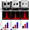
Micro-CT assessment of newly formed bone and blood vessels in rat calvarial defect regions after the implantation of scaffolds of CS, HANWs/CS, and HANW@MS/ CS for 12 weeks. (A) Three-dimensional (3D) and coronal views of reconstructed calvarial images. (B) Newly formed blood vessels presented by 3D reconstructed images. Morphometric analysis was completed for the percentage of newly formed bone volume (BV/TV) (C), blood vessel number (D), and blood vessel area (E) in the defects. * p < 0.05 compared to CS scaffold; # p < 0.05 compared to HANWs/CS scaffold. Reprinted with permission from [Tuan-Wei Sun], [Hydroxyapatite nanowire@magnesium silicate core-shell hierarchical nanocomposite: synthesis and application in bone regeneration]; published by ACS (2017) [142].
Figure 14
Figure 14
Visual depiction of the experimental procedure: (a) Creating spherical silica aerogels through the sol-gel technique, (b) modifying the silica aerogel surface with APTES and incorporating the 5-FU drug, (c) applying a dextran layer to the silica aerogel surface with GA crosslinker, and (d) covering the silica aerogel surface with dextran aldehyde. Reprinted with permission from [Ecem Tiryaki], [Novel organic/inorganic hybrid nanoparticles as enzyme-triggered drug delivery systems: Dextran and Dextran aldehyde coated silica aerogels]; published by Elsevier (2020) [151].

References

    1. Mazrouei-Sebdani Z., Begum H., Schoenwald S., Horoshenkov K.V., Malfait W.J. A review on silica aerogel-based materials for acoustic applications. J. Non-Cryst. Solids. 2021;562:120770. doi: 10.1016/j.jnoncrysol.2021.120770. - DOI
    1. Duan Y., Jana S.C., Lama B., Espe M.P. Reinforcement of silica aerogels using silane-end-capped polyurethanes. Langmuir. 2013;29:6156–6165. doi: 10.1021/la4007394. - DOI - PubMed
    1. Parale V.G., Lee K.-Y., Park H.H. Flexible and transparent silica aerogels: An overview. J. Korean Ceram. Soc. 2017;54:184–199. doi: 10.4191/kcers.2017.54.3.12. - DOI
    1. Zhong L., Chen X., Song H., Guo K., Hu Z. Highly flexible silica aerogels derived from methyltriethoxysilane and polydimethylsiloxane. New J. Chem. 2015;39:7832–7838. doi: 10.1039/C5NJ01477H. - DOI
    1. Li X., Dong G., Liu Z., Zhang X. Polyimide aerogel fibers with superior flame resistance, strength, hydrophobicity, and flexibility made via a universal sol–gel confined transition strategy. ACS Nano. 2021;15:4759–4768. doi: 10.1021/acsnano.0c09391. - DOI - PubMed

LinkOut - more resources