

Visualization and Experimental Characterization of Wrapping Layer Using Planar Laser-Induced Fluorescence
- PMID: 38277478
- PMCID: PMC10851937
- DOI: 10.1021/acsnano.3c07407
Visualization and Experimental Characterization of Wrapping Layer Using Planar Laser-Induced Fluorescence
Abstract
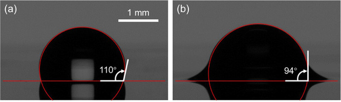
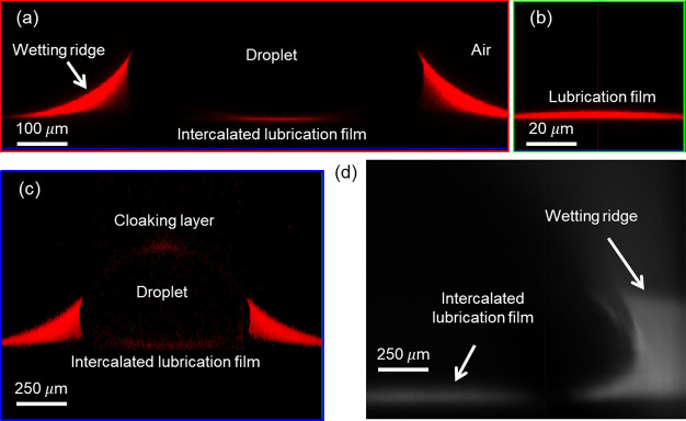
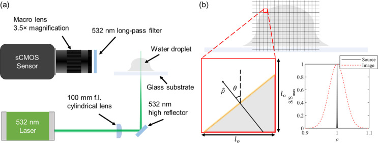
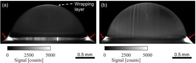
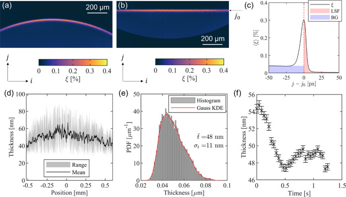
Droplets on nanotextured oil-impregnated surfaces have high mobility due to record-low contact angle hysteresis (∼1-3°), attributed to the absence of solid-liquid contact. Past studies have utilized the ultralow droplet adhesion on these surfaces to improve condensation, reduce hydrodynamic drag, and inhibit biofouling. Despite their promising utility, oil-impregnated surfaces are not fully embraced by industry because of the concern for lubricant depletion, the source of which has not been adequately studied. Here, we use planar laser-induced fluorescence (PLIF) to not only visualize the oil layer encapsulating the droplet (aka wrapping layer) but also measure its thickness since the wrapping layer contributes to lubricant depletion. Our PLIF visualization and experiments show that (a) due to the imbalance of interfacial forces at the three-phase contact line, silicone oil forms a wrapping layer on the outer surface of water droplets, (b) the thickness of the wrapping layer is nonuniform both in space and time, and (c) the time-average thickness of the wrapping layer is ∼50 ± 10 nm, a result that compares favorably with our scaling analysis (∼50 nm), which balances the curvature-induced capillary force with the intermolecular van der Waals forces. Our experiments show that, unlike silicone oil, mineral oil does not form a wrapping layer, an observation that can be exploited to mitigate oil depletion of nanotextured oil-impregnated surfaces. Besides advancing our mechanistic understanding of the wrapping oil layer dynamics, the insights gained from this work can be used to quantify the lubricant depletion rate by pendant droplets in dropwise condensation and water harvesting.
Keywords: lubricant-impregnated surfaces (LIS); oil-infused surfaces; planar laser-induced fluorescence (PLIF); slippery liquid-infused porous surfaces (SLIPS); spreading coefficient; wetting ridge; wrapping layer.
Conflict of interest statement
The authors declare no competing financial interest.
Figures
Similar articles
-
Wetting Ridge Growth Dynamics on Textured Lubricant-Infused Surfaces.ACS Appl Mater Interfaces. 2025 May 28;17(21):31677-31684. doi: 10.1021/acsami.4c20298. Epub 2025 May 8. ACS Appl Mater Interfaces. 2025. PMID: 40338727 Free PMC article.
-
Direct Measurement and Modeling of Wrapping Layer on Lubricant-Infused Surfaces.ACS Appl Mater Interfaces. 2025 Aug 27;17(34):48895-48903. doi: 10.1021/acsami.5c09883. Epub 2025 Aug 14. ACS Appl Mater Interfaces. 2025. PMID: 40810421
-
Depletion of Lubricant from Nanostructured Oil-Infused Surfaces by Pendant Condensate Droplets.ACS Nano. 2020 Jul 28;14(7):8024-8035. doi: 10.1021/acsnano.9b10184. Epub 2020 Jun 17. ACS Nano. 2020. PMID: 32490664
-
Wetting ridges on slippery liquid-infused porous surfaces.Rep Prog Phys. 2023 May 22;86(6). doi: 10.1088/1361-6633/acc87a. Rep Prog Phys. 2023. PMID: 36990071 Review.
-
Life and death of liquid-infused surfaces: a review on the choice, analysis and fate of the infused liquid layer.Chem Soc Rev. 2020 Jun 8;49(11):3688-3715. doi: 10.1039/d0cs00036a. Chem Soc Rev. 2020. PMID: 32396597 Review.
Cited by
-
Wetting Ridge Growth Dynamics on Textured Lubricant-Infused Surfaces.ACS Appl Mater Interfaces. 2025 May 28;17(21):31677-31684. doi: 10.1021/acsami.4c20298. Epub 2025 May 8. ACS Appl Mater Interfaces. 2025. PMID: 40338727 Free PMC article.
References
-
- Bico J.; Marzolin C.; Quéré D. Pearl drops. Europhys. Lett. 1999, 47 (2), 220.10.1209/epl/i1999-00548-y. - DOI
-
- Leslie D. C.; Waterhouse A.; Berthet J. B.; Valentin T. M.; Watters A. L.; Jain A.; Kim P.; Hatton B. D.; Nedder A.; Donovan K.; Super E. H.; Howell C.; Johnson C. P.; Vu T. L.; Bolgen D. E.; Rifai S.; Hansen A. R.; Aizenberg M.; Super M.; Aizenberg J.; Ingber D. E. A bioinspired omniphobic surface coating on medical devices prevents thrombosis and biofouling. Nat. Biotechnol. 2014, 32 (11), 1134–1140. 10.1038/nbt.3020. - DOI - PubMed
-
- Kolle S.; Ahanotu O.; Meeks A.; Stafslien S.; Kreder M.; Vanderwal L.; Cohen L.; Waltz G.; Lim C. S.; Slocum D.; Greene E. M.; Hunsucker K.; Swain G.; Wendt D.; Teo S. L. M.; Aizenberg J. On the mechanism of marine fouling-prevention performance of oil-containing silicone elastomers. Sci. Rep. 2022, 12 (1), 1–13. 10.1038/s41598-022-15553-4. - DOI - PMC - PubMed
LinkOut - more resources
Full Text Sources
Miscellaneous
