

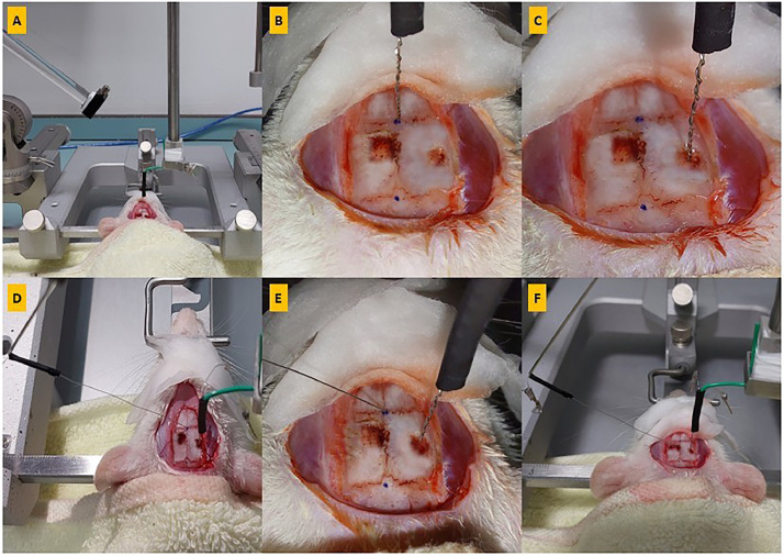
Step-by-step approach: Stereotaxic surgery for in vivo extracellular field potential recording at the rat Schaffer collateral-CA1 synapse using the eLab system
- PMID: 38283759
- PMCID: PMC10820282
- DOI: 10.1016/j.mex.2023.102544
Step-by-step approach: Stereotaxic surgery for in vivo extracellular field potential recording at the rat Schaffer collateral-CA1 synapse using the eLab system
Abstract
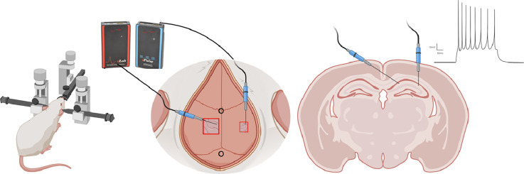
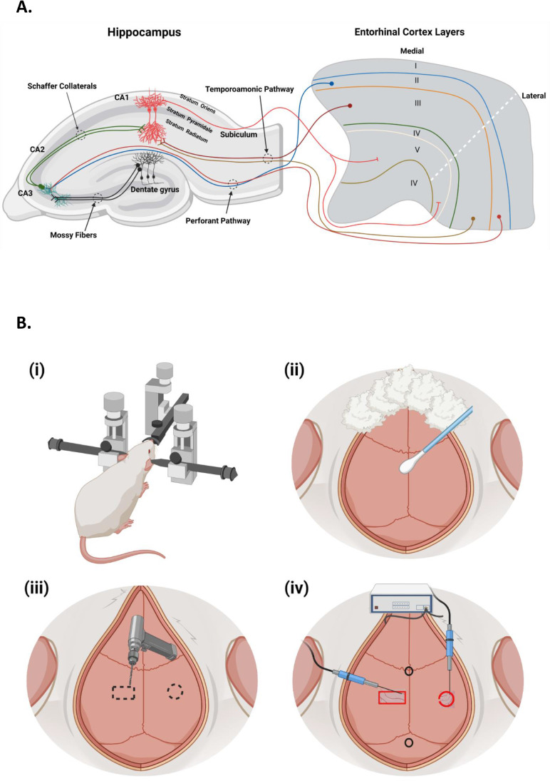
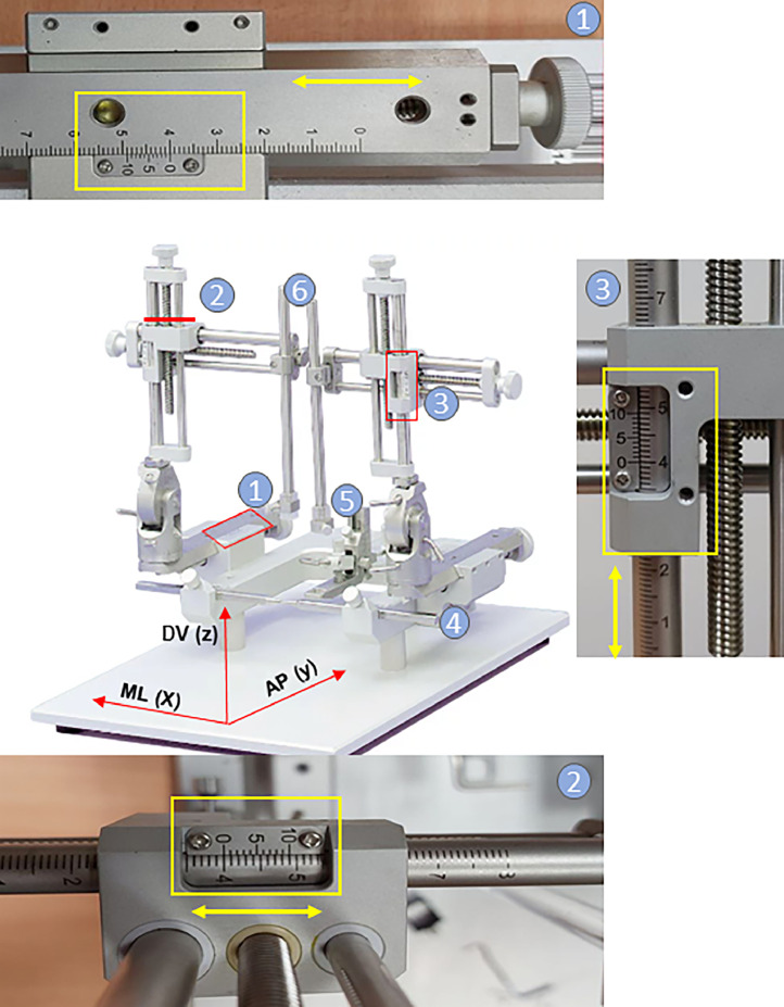
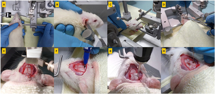
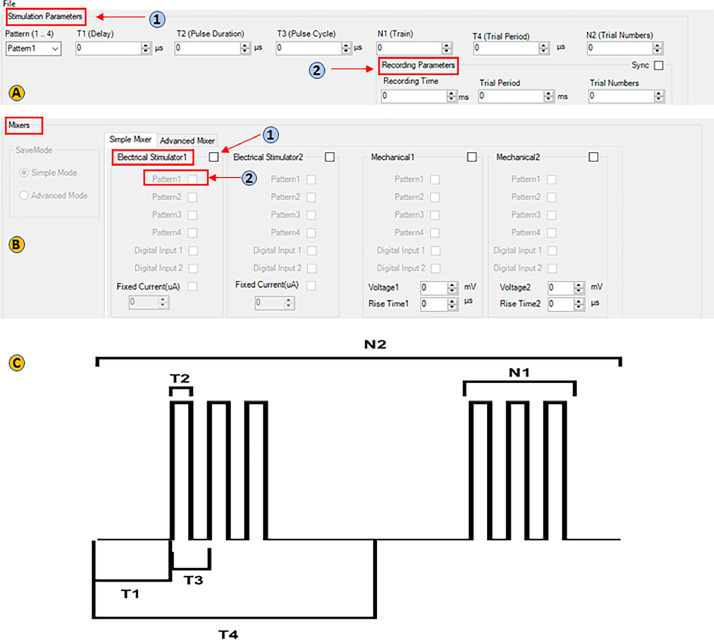
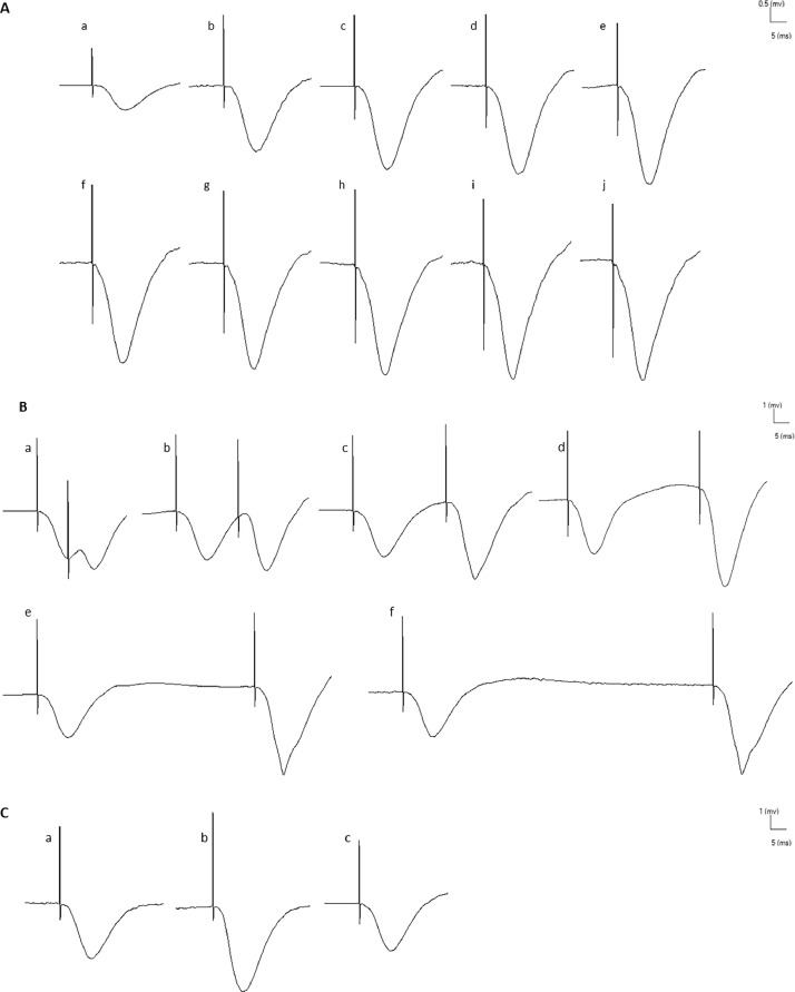
In vivo extracellular field potential recording is a commonly used technique in modern neuroscience research. The success of long-term electrophysiological recordings often depends on the quality of the implantation surgery. However, there is limited use of visually guided stereotaxic neurosurgery and the application of the eLab/ePulse electrophysiology system in rodent models. This study presents a practical and functional manual guide for surgical electrode implantation in rodent models using the eLab/ePulse electrophysiology system for recording and stimulation purposes to assess neuronal functionality and synaptic plasticity. The evaluation parameters included the input/output function (IO), paired-pulse facilitation or depression (PPF/PPD), long-term potentiation (LTP), and long-term depression (LTD).•Provides a detailed picture-guided procedure for conducting in vivo stereotaxic neurosurgery.•Specifically covers the insertion of hippocampal electrodes and the recording of evoked extracellular field potentials.
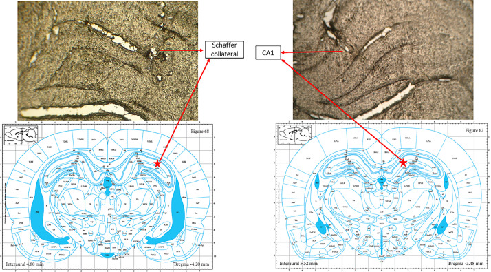
Keywords: CA1; Hippocampus; In vivo hippocampal extracellular local field potentials recording; Local field potential measurement; Schaffer collaterals; Stereotaxic techniques.
© 2023 The Author(s).
Conflict of interest statement
The authors declare that they have no known competing financial interests or personal relationships that could have appeared to influence the work reported in this paper.
Figures
Similar articles
-
[Recordings of long-term potentiation in rat hippocampal CA1 area with an electrodes-binding technique in vivo].Zhongguo Ying Yong Sheng Li Xue Za Zhi. 2007 Aug;23(3):381-4. Zhongguo Ying Yong Sheng Li Xue Za Zhi. 2007. PMID: 21162289 Chinese.
-
Investigating Long-term Synaptic Plasticity in Interlamellar Hippocampus CA1 by Electrophysiological Field Recording.J Vis Exp. 2019 Aug 11;(150). doi: 10.3791/59879. J Vis Exp. 2019. PMID: 31449262
-
The temporoammonic input to the hippocampal CA1 region displays distinctly different synaptic plasticity compared to the Schaffer collateral input in vivo: significance for synaptic information processing.Front Synaptic Neurosci. 2013 Aug 23;5:5. doi: 10.3389/fnsyn.2013.00005. eCollection 2013. Front Synaptic Neurosci. 2013. PMID: 23986697 Free PMC article.
-
[Involvement of protein tyrosine kinases in β-amyloid protein-induced suppression of long-term potentiation in the rat hippocampal CA1 region in vivo].Sheng Li Xue Bao. 2009 Jun 25;61(3):263-71. Sheng Li Xue Bao. 2009. PMID: 19536439 Chinese.
-
A distinct impact of repeated morphine exposure on synaptic plasticity at Schaffer collateral-CA1, temporoammonic-CA1, and perforant pathway-dentate gyrus synapses along the longitudinal axis of the hippocampus.Hippocampus. 2023 Jan;33(1):47-62. doi: 10.1002/hipo.23488. Epub 2022 Dec 13. Hippocampus. 2023. PMID: 36514833
Cited by
-
Artificial Intelligence and Neuroscience: Transformative Synergies in Brain Research and Clinical Applications.J Clin Med. 2025 Jan 16;14(2):550. doi: 10.3390/jcm14020550. J Clin Med. 2025. PMID: 39860555 Free PMC article. Review.
References
-
- Kesner R.P. Neurobiological foundations of an attribute model of memory. Comp. Cogn. Behav. Rev. 2013;8:29–59.
LinkOut - more resources
Full Text Sources
Miscellaneous
