. 2024 Feb 2;13(1):42.
doi: 10.1038/s41377-023-01364-3.

Stable, intense supercontinuum light generation at 1 kHz by electric field assisted femtosecond laser filamentation in air

Affiliations

Stable, intense supercontinuum light generation at 1 kHz by electric field assisted femtosecond laser filamentation in air

Yaoxiang Liu et al. Light Sci Appl. .

Abstract

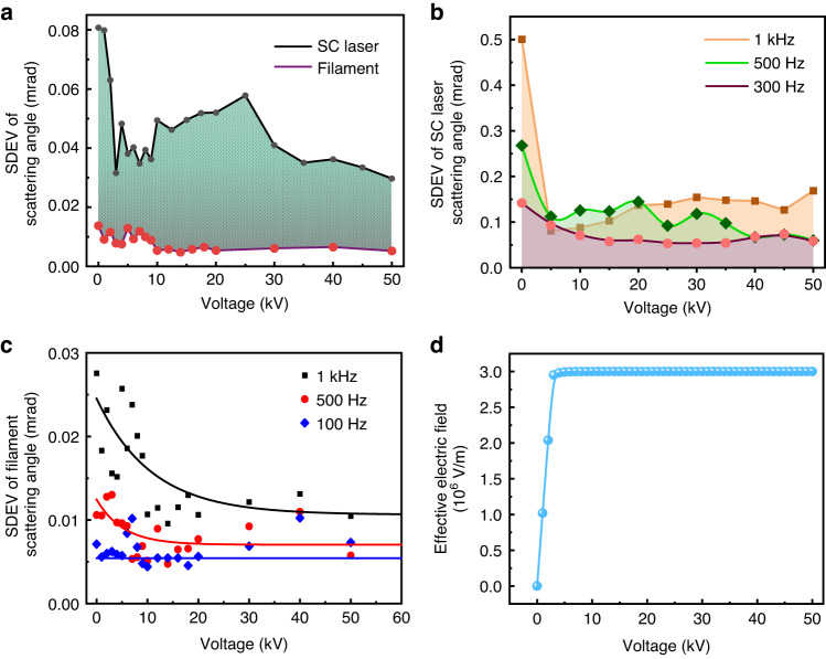
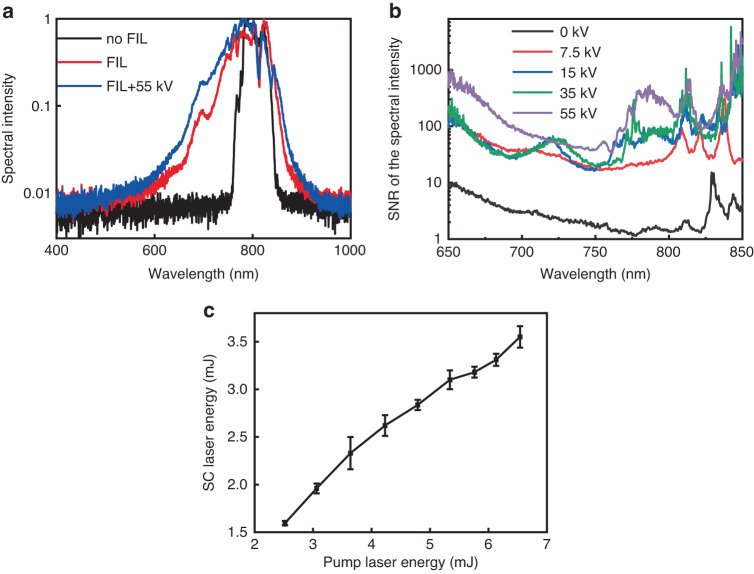
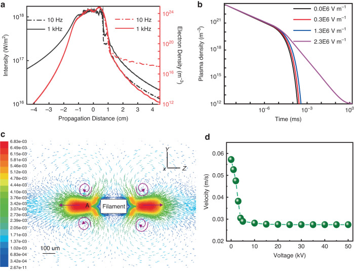
Supercontinuum (SC) light source has advanced ultrafast laser spectroscopy in condensed matter science, biology, physics, and chemistry. Compared to the frequently used photonic crystal fibers and bulk materials, femtosecond laser filamentation in gases is damage-immune for supercontinuum generation. A bottleneck problem is the strong jitters from filament induced self-heating at kHz repetition rate level. We demonstrated stable kHz supercontinuum generation directly in air with multiple mJ level pulse energy. This was achieved by applying an external DC electric field to the air plasma filament. Beam pointing jitters of the 1 kHz air filament induced SC light were reduced by more than 2 fold. The stabilized high repetition rate laser filament offers the opportunity for stable intense SC generation and its applications in air.


Conflict of interest statement

The authors declare no competing interests.

Figures

Fig. 1
Fig. 1. Schematic of experimental setups.
a Generation and characterization of stable high energy SC light in air at kHz repetition rate. b Filament jitter measurement. Real color images of laser filament in air with high voltage off c and on d. The corresponding far-field forward beam patterns on a white screen in real color: e high voltage off and f high voltage on. Laser pulse energy was 6.12 mJ and the voltage applied on the electrode was 55 kV. The distance between the electrode tip and the laser filament was approximately 1 mm. c, d and e, f have the same length scale, respectively
Fig. 2
Fig. 2. Maps of filament’s position and forward white light spots with different high voltages.
ad Filament’s position, eh forward white light spots. a, e 0 kV; b, f 2 kV; c, g 30 kV; d, h 50 kV. The position of the optical axis without filamentation and without high voltage is defined as (0, 0)
Fig. 3
Fig. 3. Pointing stability of the forward SC laser and filament as a function of the applied high voltage.
a SDEVs of the forward SC laser and filament pointing angles at 1 kHz. SDEVs of the scattering angles of forward SC light (b) and filament (c) under different laser repetition rates. Solid lines in (c) are fits for guiding the eyes. d Simulated result of the effective electric field applied on the filament as the voltage increasing
Fig. 4
Fig. 4. Experimental and numerical results of SC light and filament displacement distance under different voltages.
a SC light and b filament displacement distance in the (horizontal) plane under different applied voltages. The plane contains the electrode and the filament. Position ’0’ represents the initial mean position without the DC electric field. The negative displacement is defined as when the filament is closer to the electrode
Fig. 5
Fig. 5. Spectral stability and the energy scaling of the SC laser.
a The white light spectra after filamentation with (FIL+55kV) and without (FIL) DC electric field. The initial laser spectrum (no FIL) is for comparison. Each spectral distribution was normalized at its maximum. b The SNR of the SC spectral intensities under different applied voltages. The laser worked at 1 kHz. c The SC laser energy obtained as a function of pump laser energy under 1 m focusing condition
Fig. 6
Fig. 6. The simulation results of the on-axis plasma density and airflow around the filament.
a The simulated on-axis laser intensity, plasma density with the laser working at 10 Hz and 1000 Hz. b is the simulated time evolution of the plasma density under different electric fields. c 2D cross-section of the simulated flow fields around the filament without external electric field. The velocity vectors are colored by velocity magnitude (m s−1). The rectangle represents the longitudinal section of the cylindrical filament. The direction of the laser propagation was along the Z axis.The cross-section of the filament was in the XY plane. d is the maximum airflow velocity around the filament when applying different voltages. See the details of the simulation in the ’Methods’
Fig. 7
Fig. 7
Static electric field distribution in the horizontal plane with the filament plasma channel. The applied high voltage was 4 kV
Fig. 8
Fig. 8
Schematic diagram of the high voltage electrode controlled filament via the electric field lines as if it were a fan. R is the diameter of the filament; F1 and F2 are the attractive electric forces in the opposite direction induced by the positive high-voltage electric field and the positive ions, respectively
Fig. 9
Fig. 9
The output current as a function of the applied voltages

References

    1. Alfano RR, Shapiro SL. Observation of self-phase modulation and small-scale filaments in crystals and glasses. Phys. Rev. Lett. 1970;24:592–594. doi: 10.1103/PhysRevLett.24.592. - DOI
    1. Brabec T, Krausz F. Intense few-cycle laser fields: frontiers of nonlinear optics. Rev. Mod. Phys. 2000;72:545–591. doi: 10.1103/RevModPhys.72.545. - DOI
    1. Hentschel M, et al. Attosecond metrology. Nature. 2001;414:509–513. doi: 10.1038/35107000. - DOI - PubMed
    1. Udem T, Holzwarth R, Hänsch TW. Optical frequency metrology. Nature. 2002;416:233–237. doi: 10.1038/416233a. - DOI - PubMed
    1. Smirnov SV, et al. Optical spectral broadening and supercontinuum generation in telecom applications. Opt. Fiber Technol. 2006;12:122–147. doi: 10.1016/j.yofte.2005.07.004. - DOI