. 2024 Feb 5;15(1):1089.
doi: 10.1038/s41467-024-45232-z.

Rapid exchange cooling with trapped ions

Affiliations

Rapid exchange cooling with trapped ions

Spencer D Fallek et al. Nat Commun. .

Abstract

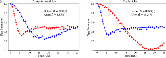
The trapped-ion quantum charge-coupled device (QCCD) architecture is a leading candidate for advanced quantum information processing. In current QCCD implementations, imperfect ion transport and anomalous heating can excite ion motion during a calculation. To counteract this, intermediate cooling is necessary to maintain high-fidelity gate performance. Cooling the computational ions sympathetically with ions of another species, a commonly employed strategy, creates a significant runtime bottleneck. Here, we demonstrate a different approach we call exchange cooling. Unlike sympathetic cooling, exchange cooling does not require trapping two different atomic species. The protocol introduces a bank of "coolant" ions which are repeatedly laser cooled. A computational ion can then be cooled by transporting a coolant ion into its proximity. We test this concept experimentally with two 40Ca+ ions, executing the necessary transport in 107 μs, an order of magnitude faster than typical sympathetic cooling durations. We remove over 96%, and as many as 102(5) quanta, of axial motional energy from the computational ion. We verify that re-cooling the coolant ion does not decohere the computational ion. This approach validates the feasibility of a single-species QCCD processor, capable of fast quantum simulation and computation.


Conflict of interest statement

The authors declare no competing interests.

Figures

Fig. 1
Fig. 1. Exchange cooling in the Peregrine trap.
Simulated axial trajectories of the computational ion and coolant ion through exchange-cooling transport. Positions are given relative to the center of the Q12/Q13 Peregrine trap electrodes. Electrodes are shown schematically in gold on the left. Axial motional energy transfers from an initially hot (red) ion to a cold (blue) ion. Top axis: Exchange transport is separated into three parts a, b, and c, which are themselves divided into smaller steps (see main text and Table 1). Inset: Modifications of the axial double-well potential V(z) through part b (not to scale). The initial off resonance double-well potential (green) is interpolated onto resonance to generate the exchange potential (orange), at which point the ions exchange energy (purple).
Fig. 2
Fig. 2. Double-well and exchange-coupling characterization.
Measurements of ion separation (a) and δΩ (b) when varying the linear and harmonic compensating potentials. (c) and (d) are corresponding simulations (see Ion Motional Simulations). The red star in (a) and (b) indicates the value of compensating potentials used for a resonant exchange.
Fig. 3
Fig. 3. Exchange cooling calibration and performance.
(a) Oscillations in axial mode temperature n¯ following exchange transport as a function of tex. Energy swaps between the computational ion (red) and the coolant ion (blue). Our procedure for determining n¯ and its uncertainty using a fixed-length sideband pulse is described in Temperature Measurements. Solid lines are simulations, as described in Ion Motional Simulations. (b) Computational ion temperature after exchange transport as the initial temperature is varied, along with a linear fit (solid black line). The blue arrow indicates the results of an experiment in which the coolant ion was re-cooled after the first exchange and a second exchange was attempted. Horizontal (vertical) error bars represent the uncertainty in ion temperature before (after) exchange transport measured using the sideband flopping method.
Fig. 4
Fig. 4. Ramsey interferometry.
(a) Experimental sequence for a Ramsey experiment on the computational ion which incorporates re-cooling of the coolant ion and exchange transport (not to scale). Composite π/2 pulses for preparation and analysis begin and end the interferometry. Between π/2 pulses, sideband cooling on the coolant ion and exchange transport are performed. These two operations (marked with hash coloring) are alternatively replaced with equivalent delays. An echo composite π pulse mitigates the impact of slow magnetic field drift. (b) Computational-ion Ramsey fringe, measured by varying the relative phase ϕ between preparation and analysis π/2 pulses. Blue points include re-cooling of the coolant ion and exchange transport. The red points include an equivalent delay. Error bars represent the 68% confidence interval in state populations assuming binomial statistics. Solid lines are fits to the data.
Fig. 5
Fig. 5. Simulations of ion axial mode frequency.
Simulations of the computational ion mode frequency absent any Coulomb interaction as a function of double-well potential separation. Because the transport waveform is symmetric, the coolant ion mode frequency is the same.
Fig. 6
Fig. 6. Mode temperature characterization via sideband flopping.
Blue sideband flopping on the computational ion a) and coolant ion b) before (red) and after (blue) exchange transport. Error bars represent the 68% confidence interval in state populations assuming binomial statistics. Solid lines are fits to each flop, with the fitted n¯ reported.
Fig. 7
Fig. 7. Population transfer scheme for ramsey interferometry.
729 nm laser pulses on the computational ion used for Ramsey interferometry, executed from left to right. The experiment is comprised of three sets of pulses, (a) preparation, (b) echo and (c) analysis, described in Box 1. Circles indicate the ion state population before and after each set of pulses. The filled circle represents complete population in the 1/2 state. Half circles indicate 50/50 superpositions between the +1/2,1/2 states. Population swaps between these two states during the echo sequence. Hashed circles represent a superposition of the 1/2 and D states.

References

    1. Kim Y, et al. Evidence for the utility of quantum computing before fault tolerance. Nature. 2023;618:500–505. doi: 10.1038/s41586-023-06096-3. - DOI - PMC - PubMed
    1. Moses SA, et al. A Race-Track Trapped-Ion Quantum Processor. Phys. Rev. X. 2023;13:041052.
    1. Ebadi S, et al. Quantum phases of matter on a 256-atom programmable quantum simulator. Nature. 2021;595:227–232. doi: 10.1038/s41586-021-03582-4. - DOI - PubMed
    1. Kielpinski D, Monroe C, Wineland DJ. Architecture for a large-scale ion-trap quantum computer. Nature. 2002;417:709–711. doi: 10.1038/nature00784. - DOI - PubMed
    1. Bowler R, et al. Coherent Diabatic Ion Transport and Separation in a Multizone Trap Array. Phys. Rev. Lett. 2012;109:080502. doi: 10.1103/PhysRevLett.109.080502. - DOI - PubMed

LinkOut - more resources