. 2024 Sep;11(Suppl 1):S11503.
doi: 10.1117/1.NPh.11.S1.S11503. Epub 2024 Feb 6.

Photonic neural probe enabled microendoscopes for light-sheet light-field computational fluorescence brain imaging

Affiliations

Photonic neural probe enabled microendoscopes for light-sheet light-field computational fluorescence brain imaging

Peisheng Ding et al. Neurophotonics. 2024 Sep.

Abstract

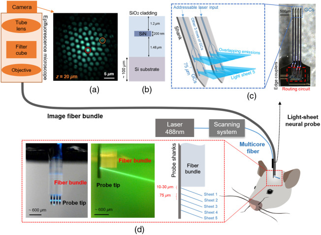
Significance: Light-sheet fluorescence microscopy is widely used for high-speed, high-contrast, volumetric imaging. Application of this technique to in vivo brain imaging in non-transparent organisms has been limited by the geometric constraints of conventional light-sheet microscopes, which require orthogonal fluorescence excitation and collection objectives. We have recently demonstrated implantable photonic neural probes that emit addressable light sheets at depth in brain tissue, miniaturizing the excitation optics. Here, we propose a microendoscope consisting of a light-sheet neural probe packaged together with miniaturized fluorescence collection optics based on an image fiber bundle for lensless, light-field, computational fluorescence imaging.

Aim: Foundry-fabricated, silicon-based, light-sheet neural probes can be packaged together with commercially available image fiber bundles to form microendoscopes for light-sheet light-field fluorescence imaging at depth in brain tissue.

Approach: Prototype microendoscopes were developed using light-sheet neural probes with five addressable sheets and image fiber bundles. Fluorescence imaging with the microendoscopes was tested with fluorescent beads suspended in agarose and fixed mouse brain tissue.

Results: Volumetric light-sheet light-field fluorescence imaging was demonstrated using the microendoscopes. Increased imaging depth and enhanced reconstruction accuracy were observed relative to epi-illumination light-field imaging using only a fiber bundle.

Conclusions: Our work offers a solution toward volumetric fluorescence imaging of brain tissue with a compact size and high contrast. The proof-of-concept demonstrations herein illustrate the operating principles and methods of the imaging approach, providing a foundation for future investigations of photonic neural probe enabled microendoscopes for deep-brain fluorescence imaging in vivo.

Keywords: integrated optics; lensless imaging; light-sheet fluorescence microscopy; microendoscopes; neural probes; neurophotonics.


Figures

Fig. 1
Fig. 1
Light-sheet light-field microendoscope system. The imaging system consists of a microendoscope formed from an image fiber bundle (for fluorescence collection) with an attached implantable photonic neural probe at the distal fiber end (for delivery of excitation light) and a widefield/epifluorescence microscope for imaging fluorescence patterns at the proximal fiber bundle facet. Laser light (λ=488  nm) is coupled to the on-chip silicon nitride (SiN) waveguide circuitry of the neural probe via a custom visible-light multicore optical fiber with individual cores addressed by an optical scanning system; the probe subsequently emits addressable light sheets at the tip of the microendoscope. The mouse illustration was adapted from Ref. . (a) Proximal fiber bundle facet raw image of a fluorescent bead (10  μm diameter) at an axial distance (z) of 20  μm from the distal fiber bundle facet showing the defocused fluorescence collection and increased coupling to higher-order optical modes in the peripheral fiber bundle cores within the defocused bead image. The fiber bundle image contains both intensity and angular information of the incident light, enabling volumetric reconstructions via light-field imaging algorithms. Two fiber bundle cores showing different optical mode patterns are encircled. (b) Cross-section illustration of the neural probe chips (not to scale). (c) Micrograph of a fabricated neural probe chip (right) and illustration of light sheet generation from the SiN grating coupler (GC) emitters (left). Five rows of GCs were integrated onto 100-μm thick, 3-mm-long shanks, and light sheets are synthesized from the overlapping emissions from the GCs within each row. To achieve wide, thin sheets, the GCs were designed to emit beams of large divergence along the sheet width axis and small divergence along the sheet thickness axis. (d) Photographs of the microendoscope emitting a light sheet: front view in air (left) and side view in fluorescein (middle). Schematic showing the relative positions of the light sheets and fiber bundle in the microendoscope (right). The micrographs in panels (a) and (c), fluorescein image in panel (d), and neural probe illustrations in panels (c) and (d) were adapted from our conference abstract; see Ref. .
Fig. 2
Fig. 2
Light-sheet light-field microendoscope imaging of fluorescent beads suspended in agarose. (a) Photographs showing the microendoscope inserted into a block of agarose (left), raw fiber bundle facet images after interpolation between cores (middle), and regions of interest (ROIs) (right) comparing the same cluster of beads using epi- versus light-sheet illumination. The scale bars are 15  μm. (b) Reconstructed volume of 512  μm×512  μm×200  μm (xyz) for epi-illumination (left). Superimposed reconstructed volumes of 512  μm×512  μm×250  μm for sequential illumination from sheets 1 to 4 (right). The dashed yellow lines delineate the estimated trajectories (center lines) of the light sheets based on the beads identified within the reconstructed volumes of each sheet. The z-axis (depth) has been stretched for improved visibility of the beads. (a) and (b) Brightness- and contrast- adjusted to enhance visibility. Microendoscope 1 was used for these imaging tests. The photographs and raw images in panel (a) and the volume reconstructions in panel (b) were adapted from our conference abstract; see Ref. .
Fig. 3
Fig. 3
Light-sheet light-field fluorescence imaging of fixed brain tissue from a Thy1-GCaMP6s mouse. (a) Widefield fluorescence microscope image of the target region of the brain slice without the microendoscope. (b) Fiber bundle raw fluorescence image (after core interpolation) of the target region with epi-illumination through the bundle. (c) Volumetric confocal microscope image at the same region with a field of view of 640  μm×640  μm, an axial depth spanning 0 to 50.52  μm, and two ROIs (d) at different depths z (delineated by blue and red rectangles). The yellow overlays in panel (d) indicate neuron soma outlines and were generated via thresholding of the raw images. (e) and (f) Schematics and photographs of the two LSLF imaging geometries investigated: (e) “separate insertions” of the neural probe and fiber bundle (sheets parallel to the bundle facet) and (f) “direct microendoscope insertion” with the probe attached to the bundle (oblique light sheets). Microendoscope 3 was used for the latter imaging tests. Phosphate-buffered saline (PBS) was applied to the surfaces of the brain slices during imaging. (g) LSLF reconstructed images with the separate insertions approach at z=20 and 25  μm. The yellow neuron outlines from (d) (confocal imaging) have been manually aligned and overlaid onto (g). The bars at the bottom and right of (g) indicate maximum intensity projections (MIPs) along both axes (xz- and yz-plane MIPs, z spans 0 to 75  μm). Panels (d) and (g) have been scaled in size and brightness for visibility. Raw images corresponding to (g) are shown in Fig. S11 in the Supplementary Material. (h) Direct microendoscope insertion raw image after core interpolation and LSLF reconstructed image at z=70  μm. (i) Illustration (not to scale) showing a small region close to the shanks and corresponding to the dashed rectangles in panel (h); no patterns consistent with neuron soma were observed outside this region for the direct microendoscope insertion.

References

    1. Aharoni D., Hoogland T. M., “Circuit investigations with open-source miniaturized microscopes: past, present and future,” Front. Cell. Neurosci. 13(141) (2019). 10.3389/fncel.2019.00141 - DOI - PMC - PubMed
    1. Dunst S., Tomancak P., “Imaging flies by fluorescence microscopy: principles, technologies, and applications,” Genetics 211, 15–34 (2019). 10.1534/genetics.118.300227 - DOI - PMC - PubMed
    1. Zhao W., et al. , “Sparse deconvolution improves the resolution of live-cell super-resolution fluorescence microscopy,” Nat. Biotechnol. 40, 606–617 (2021). 10.1038/s41587-021-01092-2 - DOI - PubMed
    1. Yu C.-H., et al. , “Diesel2p mesoscope with dual independent scan engines for flexible capture of dynamics in distributed neural circuitry,” Nat. Commun. 12(1), 6639 (2021). 10.1038/s41467-021-26736-4 - DOI - PMC - PubMed
    1. Zong W., et al. , “Large-scale two-photon calcium imaging in freely moving mice,” Cell 185(7), 1240–1256.e30 (2022). 10.1016/j.cell.2022.02.017 - DOI - PMC - PubMed