. 2024 Feb 9;10(6):eadi7840.
doi: 10.1126/sciadv.adi7840. Epub 2024 Feb 7.

Rac1 promotes kidney collecting duct repair by mechanically coupling cell morphology to mitotic entry

Affiliations

Rac1 promotes kidney collecting duct repair by mechanically coupling cell morphology to mitotic entry

Fabian Bock et al. Sci Adv. .

Abstract

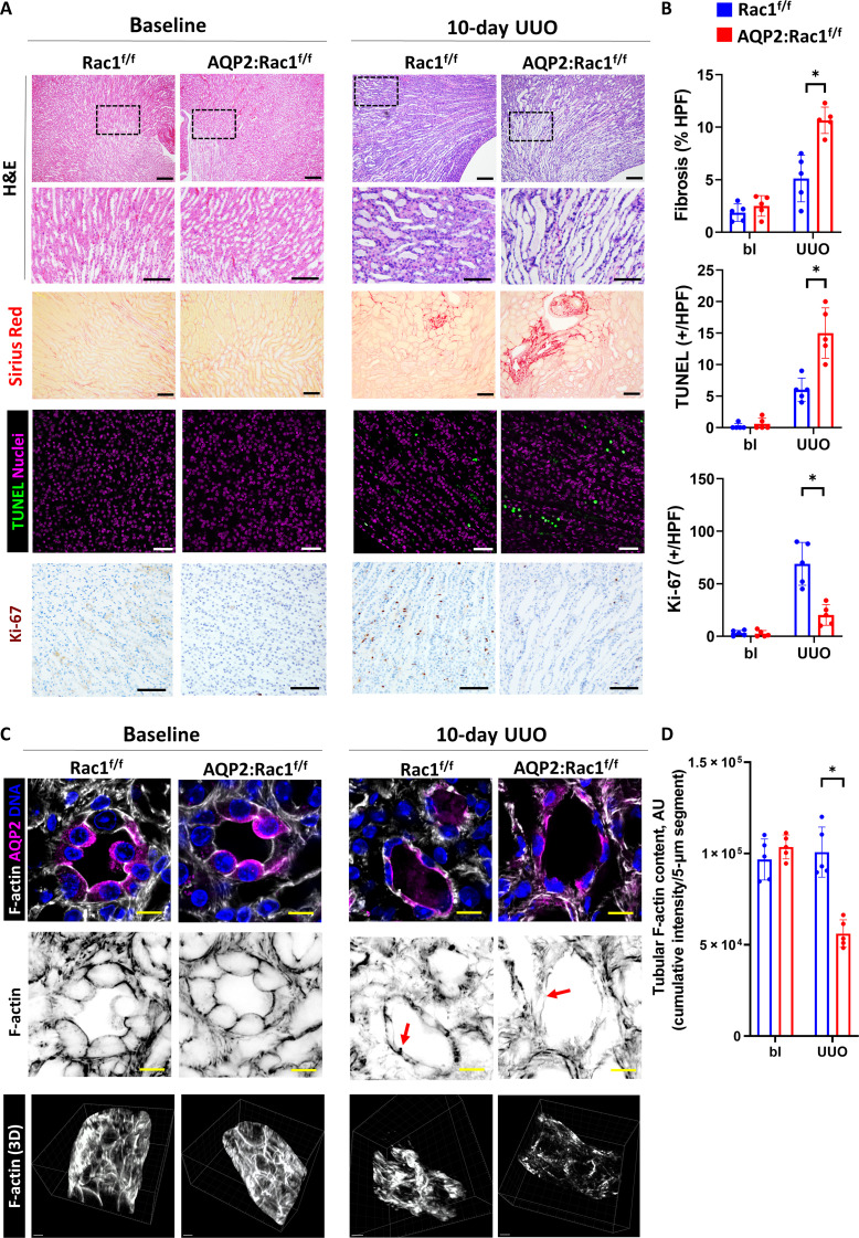
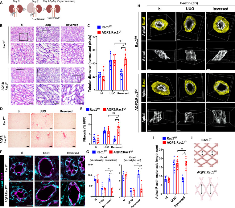
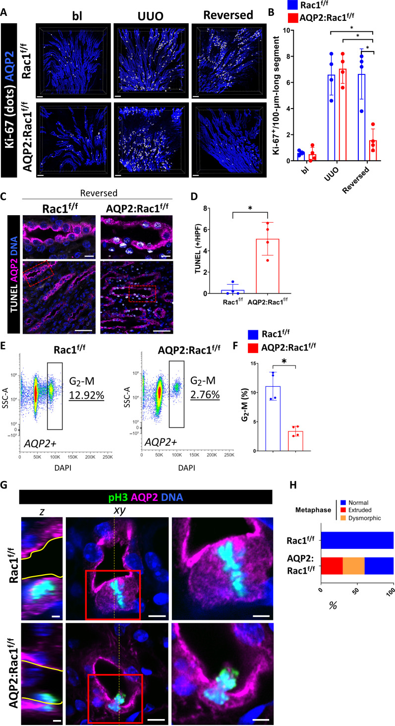
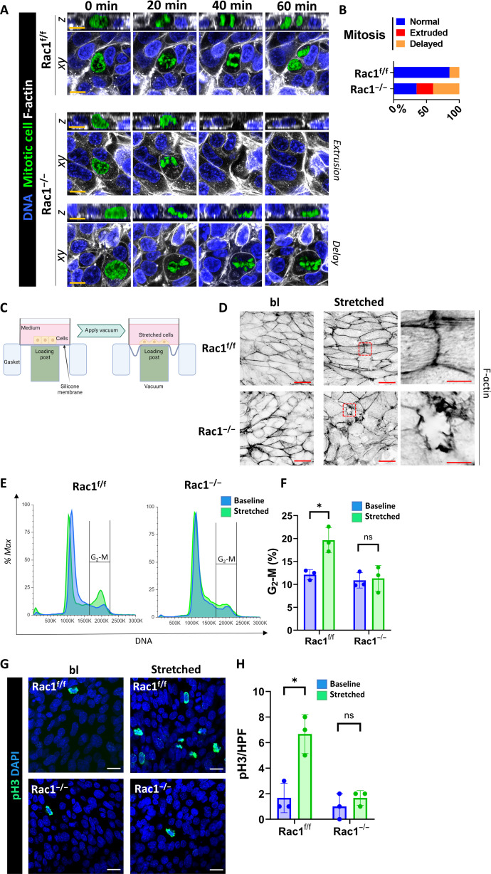
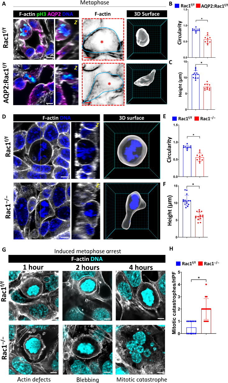
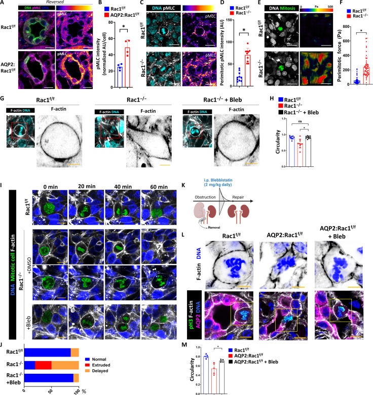
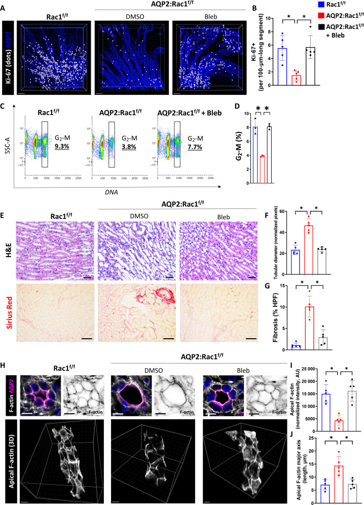
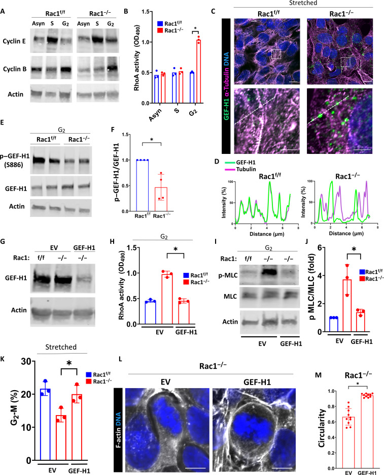
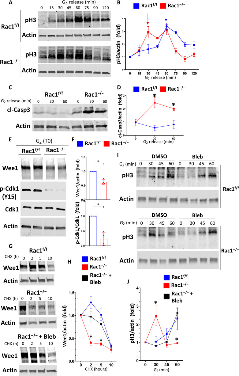
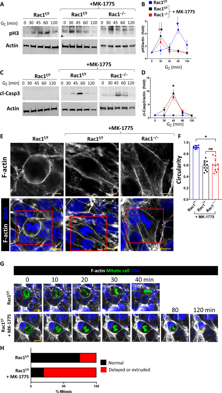
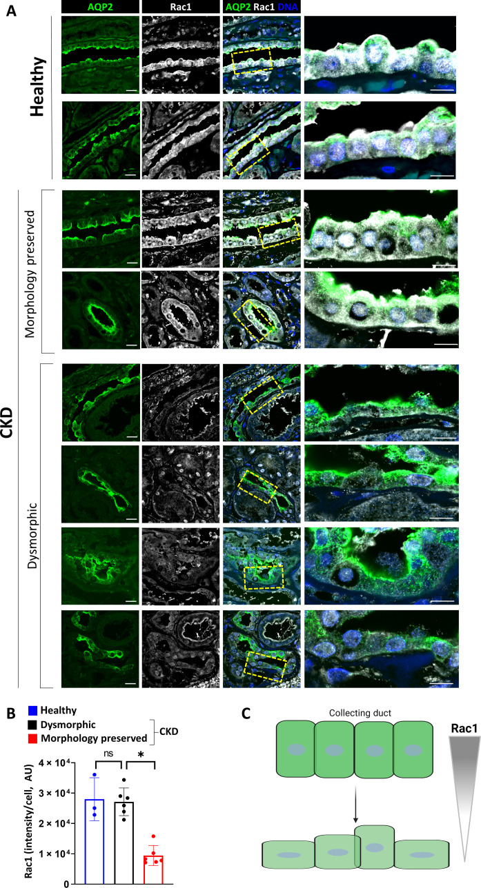
Prolonged obstruction of the ureter, which leads to injury of the kidney collecting ducts, results in permanent structural damage, while early reversal allows for repair. Cell structure is defined by the actin cytoskeleton, which is dynamically organized by small Rho guanosine triphosphatases (GTPases). In this study, we identified the Rho GTPase, Rac1, as a driver of postobstructive kidney collecting duct repair. After the relief of ureteric obstruction, Rac1 promoted actin cytoskeletal reconstitution, which was required to maintain normal mitotic morphology allowing for successful cell division. Mechanistically, Rac1 restricted excessive actomyosin activity that stabilized the negative mitotic entry kinase Wee1. This mechanism ensured mechanical G2-M checkpoint stability and prevented premature mitotic entry. The repair defects following injury could be rescued by direct myosin inhibition. Thus, Rac1-dependent control of the actin cytoskeleton integrates with the cell cycle to mediate kidney tubular repair by preventing dysmorphic cells from entering cell division.


Figures

Fig. 1.
Fig. 1.. Rac1 is required to maintain epithelial and F-actin integrity during prolonged obstruction.
(A) Hematoxylin and eosin (H&E)–stained paraffin kidney sections in the first and second rows [scale bars, 100 μm (top row) and 50 μm (insets); area for insets indicated by a black dashed box), Sirius Red staining in the third row (scale bars, 50 μm), apoptosis [terminal deoxynucleotidyl transferase–mediated deoxyuridine triphosphate nick end labeling (TUNEL)] staining in the fourth row (nuclei are magenta, and positive nuclei are green; scale bars, 50 μm), and Ki-67 in the fifth row [3,3′-Diaminobenzidine (DAB), brown; scale bars, 50 μm] of medullary regions of control (Rac1f/f) or AQP2:Rac1f/f kidneys at baseline or 10 days after obstruction (10-day UUO, ureteral ligation with sutures). (B) Quantification of fibrosis [as percentage of Sirius Red–positive area per high-power field (HPF)], TUNEL (positive cells per HPF), and Ki-67 (positive cells per HPF) from (A). bl, baseline. (C) Thick fresh frozen medullary kidney slices stained for AQP2 (CDs) and F-actin of baseline and obstructed (10-day UUO) control and AQP2:Rac1f/f kidneys. First row depicts a cross section (scale bars, 10 μm), second row shows the F-actin channel with the colors inverted (scale bars, 10 μm), and the third row shows 3D F-actin reconstructions (scale bars, 5 μm). Red arrows in the second row highlight basolateral F-actin that is deficient in the injured mutant CDs. (D) Quantification of total tubular F-actin content as outlined in the methods. AU, arbitrary units. n = 5 mice per group with each dot in the scatter plots representing an individual sample. Bars are means ± SD. *P < 0.05.
Fig. 2.
Fig. 2.. Rac1 promotes CD repair, morphological reconstitution, and F-actin recovery.
(A) Schematic representation of the reversible UUO model outlining surgical clamp placement and removal for collecting system decompression. (B) H&E paraffin kidney sections of Rac1f/f and AQP2:Rac1f/f mice at baseline, after 5 days of UUO and 1 week after reversal of obstruction (“reversed”) in the top row (scale bars, 50 μm) with a black dashed box indicating insets shown below (scale bars, 20 μm). (C) Quantification of medullary tubular diameter in (B) in normalized pixels (normalized to frame size that was equal between groups). (D) Sirius Red stained kidney sections (scale bars, 100 μm). (E) Quantification of fibrosis in (D) as percent Sirius Red positive per HPF. (F) E-cadherin immunostaining was performed on paraffin kidney sections of baseline, obstructed, and reversed Rac1f/f and AQP2:Rac1f/f mice, and the CDs were marked by AQP2 (scale bars, 10 μm); sections were analyzed by confocal microscopy. (G) Quantification of normalized lateral E-cadherin intensity (left) and lateral E-cadherin height in micrometers (right) from (F) using ImageJ. (H) 3D reconstructions of AQP2-positive F-actin–labeled CDs with segmentation and masking of the basolateral (yellow) and apical (white) F-actin using Imaris. Top rows display a top view of both masking channels, and bottom rows show side views of apical F-actin. n = 6 mice per group. Scale bars, 5 μm. (I) Quantification of the apical F-actin major axis length in micrometers (details in Materials and Methods) with each dot in the scatter plots representing measurements. (J) Schematic depiction of the results showing abnormal longitudinal extension of the apical F-actin meshwork of repairing AQP2:Rac1f/f CDs. Bars are means ± SD. ns, not significant. *P < 0.05. Panels (A) and (J) were created with Biorender.com.
Fig. 3.
Fig. 3.. Rac1 promotes proliferation and normal mitotic progression during repair.
(A) Optically cleared full medullary slices of baseline, obstructed (“UUO”), and unobstructed reversed Rac1f/f and AQP2:Rac1f/f kidneys. Ki-67 signal inside AQP2+ CDs was filtered and converted to white dots. Scale bars, 100 μm. (B) Quantification of (A) showing Ki-67–positive cells per 100-μm-long CD segment with each dot representing individual mice. n = 4 mice per group. (C) Apoptosis (TUNEL; white) labeling of CDs (AQP2+; magenta) of paraffin kidney sections in reversed Rac1f/f and AQP2:Rac1f/f mice. (D) Quantification of TUNEL-positive cells in CDs per medullary HPF with each dot representing individual samples. n = 4 mice per group. (E) Representative flow cytometry plots of AQP2+ CD cells of reversed Rac1f/f and AQP2:Rac1f/f kidneys showing side scatter (SSC-A) against DNA [4′,6-diamidino-2-phenylindole (DAPI)] with a G2-M phase–specific cell cycle gate and corresponding subpopulation percentage shown in the plot. (F) Quantification of G2-M phase–specific cell populations as shown in the gating in (E) with four mice (dots) per group; bars are means ± SD. (G) Mitotic (pH3-positive; green) metaphase cells (condensed, aligned DNA) of repairing (reversed) CDs (AQP2; magenta) of Rac1f/f and AQP2:Rac1f/f mice were analyzed using 3D super-resolution confocal imaging. The far left column shows orthogonal Z-slices (scale bars, 2.5 μm; yellow continuous line outlines the apical lumen) as indicated by the yellow dashed line in the cross section in the middle column (scale bars, 5 μm). The far right column depicts insets as outlined by a red continuous box (scale bars, 2.5 μm). (H) Relative distribution of metaphase abnormalities based on a morphological assessment as shown in (G). At least 10 mitoses were analyzed per group. *P < 0.05.
Fig. 4.
Fig. 4.. Rac1 promotes mitotic progression, F-actin integrity, and a G2-M cell cycle shift after CD cell injury in vitro.
(A) Live confocal mitosis imaging of SPY650-DNA (blue)– and SPY555-actin (white)–labeled CD cells in vitro. Orthogonal Z-slices are also shown. Representative mitotic defects are shown for Rac1−/− CD cells. Scale bars, 10 μm. The mitotic cell was manually recolored in green. (B) Relative distribution of mitotic defects in vitro during live imaging cell division sequences with at least 10 mitoses analyzed per group. (C) Schematic presentation of the Flexcell bioreactor. Created with Biorender.com (D) Super-resolution confocal images of apical cross sections of phalloidin-647 (F-actin)–labeled Rac1f/f and Rac1−/− CD cell monolayers before stretch (baseline) and after stretch (“stretched”). Images are shown as color-inverted grayscale images and are representative of three repeat experiments (scale bars, 20 μm). The red dashed box indicates the region of the inset shown in the rightmost column (scale bars, 5 μm). (E) Representative flow cytometry cell cycle histograms of propidium iodide (“DNA”)–labeled CD cells in vitro before stretch (baseline; blue) and after stretch (stretched, green). Plots are normalized to mode (% max), and the indicated range highlights the G2-M population. (F) Quantification of the relative G2-M population with bars as means ± SD and each dot representing individual samples from three independent repeat experiments. (G) Baseline and poststretch (stretched) Rac1f/f and Rac1−/− CD cell monolayers were stained for mitotic cells (pH3; green) and nuclei (DNA; blue). Images are representative of three experiments. Scale bars, 20 μm. (H) Quantification of mitotic cells (pH3-positive) per HPF of Rac1f/f and Rac1−/− CD cells before stretch (baseline; blue) and after stretch (stretched; green). Individual dots represent repeat experiments, and bars are means ± SD. *P < 0.05.
Fig. 5.
Fig. 5.. Rac1 regulates normal mitotic metaphase rounding.
(A) Cross sections of F-actin–labeled (white) thick frozen sections. CDs (AQP2; magenta) and mitotic metaphase cells (pH3; green) of reversed/repairing mice (scale bars, 5 μm). Orthogonal Z-slices of the mitotic cells are shown next to the cross section as indicated by the yellow (“z”). The red dashed box indicates color-inverted mitotic metaphase F-actin outlined by a continuous cyan line (scale bars, 3 μm). The rightmost panel shows 3D reconstructions of the metaphase F-actin (scale bars, 3 μm). Images are representative of at least 10 mitotic figures per group pooled from at least three mice per group. (B and C) Quantification of metaphase circularity (4π × area/perimeter2) and height (in micrometers) showing a minimum of 10 measurements per group. Bars are means ± SD. (D) In vitro confocal imaging of F-actin (white)– and DNA (blue)–labeled mitotic metaphase CD cells (scale bars, 5 μm). Orthogonal Z-views are shown next to the cross section with the Z-level indicated by a yellow dashed line. 3D metaphase F-actin surface reconstructions are shown (scale bars, 3 μm). (E and F) Quantification of metaphase circularity and height (in micrometers) of control and Rac1−/− CD cells showing a minimum of 10 measurements per group over at least three experiments. Bars are means ± SD. (G) F-actin (white)– and DNA (cyan)–labeled metaphase-arrested [using nocodazole (100 ng/ml), condensed chromosomes] Rac1f/f and Rac1−/− CD cells analyzed by confocal microscopy over time as indicated. Metaphase defects of Rac1−/− CD cells are shown including F-actin disorganization, surface blebbing, and nuclear fragmentation with micronuclei formation indicative of mitotic catastrophes (scale bars, 5 μm). Images are representative of at least two experiments. (H) Quantification of mitotic catastrophes per HPF of nocodazole-arrested control and Rac1−/− CD cells showing a minimum of 12 measurements per group. Bars are means ± SD. *P < 0.05.
Fig. 6.
Fig. 6.. Rac1 promotes mitotic rounding by regulating actomyosin.
(A) Representative images of activated actomyosin (pMLC) in reversed mice. CDs are labeled with DBA (dolichus biflorus agglutinin; green). pMLC is shown with a fire color scheme applied. (B) Quantification of average pMLC intensity with dots representing four mice per group. (C) pMLC (white)– and DNA (cyan)–labeled CD cell monolayers with a metaphase shown in the center. A pMLC fire color conversion is shown. Three repeat experiments. Scale bars, 20 μm (A and C). (D) pMLC intensity in the perimitotic area with dots representing 10 individual measurements. (E) F-actin (white)– and DNA (cyan)–labeled CD cells grown on a Matrigel-coated polydimethylsiloxane (PDMS) substrate with fluorescent nanobeads. Mitotic cell colored in green. Traction force maps are shown (in pascals). Scale bars, 20 μm. (F) Quantification of perimitotic forces. (G) F-actin (white)– and DNA (cyan)–labeled mitotic metaphase CD cells. Bleb, blebbistatin (5 μM). Scale bars, 10 μm. Red box outlines Metaphase F-actin shape shown on the right (scale bar, 5 μm). (H) Circularity quantification of mitotic metaphase F-actin as shown in (G). A minimum of 10 measurements are shown per group. (I) Live confocal mitosis imaging of CD cells in vitro. Bleb, 5 μM. Scale bars, 10 μm. The mitotic cell was colored in green. (J) Relative distribution of mitotic defects in vitro. At least 10 mitoses per group. In vitro experiments are representative of n = 3. (K) In vivo injection protocol of blebbistatin [5 days, 2 mg/kg per day, intraperitoneally (i.p.)]. Created with Biorender.com. (L) Super-resolution confocal imaging of mitotic CD cells during repair (scale bars, 10 μm). The yellow box outlines the insets that are shown in the top row, which depict color-inverted metaphase F-actin (scale bars, 5 μm). (M) Quantification of mitotic metaphase circularity from (L) showing n = 4 mice per group. Bars are means ± SD. *P < 0.05.
Fig. 7.
Fig. 7.. Actomyosin inhibition reversed the repair defect of AQP2:Rac1−/− mice.
(A) Optically cleared medullary slices of reversed (repairing) mice labeled with AQP2 (CDs) and Ki-67. 3D reconstructions are shown. Ki-67 signal inside AQP2+ CDs was filtered and converted to white dots. Scale bars, 100 μm. (B) Quantification of (A) showing Ki-67–positive cells per 100-μm-long CD segment with dots representing individual mice (n = 5). (C) Flow cytometry plots of AQP2+ CD cells of reversed kidneys showing side scatter (SSC-A) against DNA (DAPI) with a G2-M phase–specific cell cycle gate. Subpopulation percentages are shown in the plot. (D) Quantification of G2-M CD cells with at least three mice (one dot) per group. (E) H&E paraffin kidney sections in the first row (scale bars, 20 μm) of medullary regions and Sirius Red staining in the second row (scale bars, 50 μm). n = 5 mice per group. (F and G) Quantification of medullary tubular diameter as normalized pixels and fibrosis (as percentage of Sirius Red–positive area per HPF) with dots representing individual mice. (H) F-actin labeling (white) of CDs (AQP2; magenta) in thick fresh frozen medullary kidney slices in reversed kidneys analyzed by 3D super-resolution confocal. First row depicts two cross sections (left original, right F-actin channel; scale bars, 10 μm), and second row shows oblique views of 3D reconstructions of the apical CD F-actin (scale bars, 7 μm). (I and J) Quantification of apical F-actin intensity and apical F-actin major axis length; dots represent individual mice. n = 5 mice per group. Bars are means ± SD. *P < 0.05.
Fig. 8.
Fig. 8.. Rac1 restricts myosin activation by inhibiting the RhoA activator GEF-H1.
(A) Immunoblots of asynchronous (Asyn), G1-S–synchronized, or S phase–synchronized CD cells to confirm cell cycle phase–specific enrichment (cyclin E, S phase; cyclin B1, G2 phase). OD490, optical density at 490 nm. (B) Quantification of RhoA activity (asynchronous, S, and G2) using G-LISA and measuring absorbance at 490 nm. Individual dots represent repeat experiments (n = 3). (C) Super-resolution confocal imaging of microtubules (magenta) and GEF-H1 (green) of CD cells after stretch. Scale bars, 10 μm (first row) and 2.5 μm (second row). The white dashed box indicates the region of interest for the insets in the second row. (D) Line scan profile (white dashed line) normalized to the highest (100%) and lowest (0%) intensity. Representative of three repeat experiments and 10 measurements per group. (E and F) Immunoblotting of G2-synchronized cell lysates for phosphorylated (serine-886, S886) and total GEF-H1 in biological duplicates. Three repeat experiments were quantified in (F). Fold change values ± SD. (G) Immunoblotting of empty vector (EV)–transfected or GEF-H1 knockdown short hairpin RNA (shRNA)–transfected CD cells. (H) Quantification of RhoA activity in G2 cell cycle fractions. Individual dots represent repeat experiments (n = 3). (I and J) Immunoblotting of G2 cell cycle fractions of EV or GEF-H1 knockdown transfected for total and pMLC (serine-19). The phospho-to-total myosin light chain (pMLC–to–t-MLC) ratio is shown as fold change ± SD with individual dots representing repeat experiments (n = 3). (K) Quantification of G2-M cell cycle fractions (in percentage) of the indicated groups after induction of proliferation using stretch by flow cytometry using propidium iodide. Individual dots represent experiments (n = 3). (L and M) F-actin (white)– and DNA (blue)–labeled mitotic metaphase EV- or GEF-H1 knockdown–transfected Rac1−/− CD cells (scale bars, 5 μm). Mitotic rounding (circularity) is quantified in (M) showing a minimum of 10 measurements per group. Bars are means ± SD. *P < 0.05.
Fig. 9.
Fig. 9.. Rac1 via actomyosin regulates the G2-M checkpoint kinase Wee1 to prevent premature mitotic entry.
(A and B) CD cells were G2-synchronized using RO-3306, and lysates were collected at the indicated time points after RO-3306 washout (“G2 release”). Lysates were immunoblotted for pH3 to monitor mitotic entry. Three repeat experiments were quantified in (B). Fold change values ± SD. Arrows highlight the first pH3 peak of the respective groups indicating mitotic entry. (C and D) G2-synchronized CD cells were immunoblotted for cleaved caspase 3 (cl-Casp3) after G2 release and quantified in (D) as fold change values ± SD (n = 3). Asterisk (*) denotes between-group significance at the corresponding time point. (E and F) CD cells were G2-synchronized, and lysates were obtained immediately upon G2 washout (G2, T0) and immunoblotted in biological duplicates. p-Cdk1 Y15: phosphorylated Cdk1 tyrosine-15. Three repeat experiments were quantified in (F). Fold change values ± SD. (G and H) Asynchronous Rac1f/f (+DMSO) and Rac1−/− [+DMSO or blebbistatin (5 μM)] CD cells were treated with cycloheximide (CHX; 100 μg/ml), and lysates were obtained at the indicated time points and immunoblotted for Wee1. Three repeat experiments are quantified in (H) as fold change ± SD. Asterisk (*) denotes significance between Rac1−/− and Rac1f/f or blebbistatin-treated Rac1−/− at the corresponding time point. (I and J) Rac1f/f and Rac1−/− CD cells were G2-synchronized and treated with vehicle (DMSO) or 5 μM blebbistatin upon G2 release. Lysates were collected at the indicated time points and immunoblotted for pH3 to monitor mitotic entry. Three independent repeat experiments are quantified (for Rac1f/f, only the vehicle control is shown) in (J) as fold change values ± SD. Asterisk (*) denotes significance between Rac1−/− and Rac1f/f or blebbistatin-treated Rac1−/− at the corresponding time point. *P < 0.05.
Fig. 10.
Fig. 10.. Wee1 inhibition phenocopies Rac1 deficiency in mitosis.
(A to D) Rac1f/f and Rac1−/− CD cells were G2-synchronized using RO-3306 and treated with the Wee1-specific inhibitor MK-1775 (1 μM) upon G2 release. Lysates were collected at the indicated time points and immunoblotted for pH3 to monitor mitotic entry or cleaved caspase 3 to monitor cell death. Densitometry was used to quantify fold changes ± SD of three repeat experiments in (B) and (D). Arrows in (B) highlight the first pH3 peak indicating mitotic entry. (E) F-actin (white)– and DNA (blue)–labeled Rac1f/f and Rac1−/− (+MK-1775; 1 μM) CD cell monolayers analyzed by confocal microscopy with a mitotic metaphase cell shown in the center (scale bars, 10 μm). The top row column depicts metaphase F-actin (scale bars, 5 μm) as outlined by a red continuous box in the bottom row. Images are representative of at least three experiments. (F) Circularity quantification of mitotic metaphase F-actin as shown in (E) with a minimum of 10 measurements shown per group. Bars are means ± SD. (G) Live confocal mitosis imaging of SPY650-DNA (blue)– and SPY555-actin (white)–labeled vehicle (DMSO)– or MK-1775 (1 μM)–treated Rac1f/f CD cells in vitro. The mitotic cell was manually segmented and colored in green. Scale bars, 10 μm. Sequences are representative of three repeat experiments with at least three to four mitoses analyzed per experiment. (H) Relative distribution of mitotic defects in vitro during live imaging cell division sequences with at least 10 mitoses analyzed per group. *P < 0.05.
Fig. 11.
Fig. 11.. Rac1 is associated with preserved CD morphology in chronic kidney disease.
(A) Rac1 immunostaining (white) of human kidney biopsy specimens (paraffin) with the CDs marked by AQP2 (green). Scale bars, 20 μm. Control (“healthy”) biopsy displays a typical columnar to cuboidal CD morphology. Chronic kidney disease biopsy specimens were grouped according to CD morphology (preserved versus dysmorphic). Two or 4 representative stainings from different subjects (n = 3 healthy controls and 6 different chronic kidney disease biopsy specimens) are shown per group. The rightmost panel shows an inset that is outlined by a dashed yellow box in the original image. Scale bars, 10 μm. (B) Quantification of normalized Rac1 staining intensity per cell with dots representing the intensity per sample with 35 cells per sample analyzed. Bars are means ± SD. *P < 0.05. (C) Schematic representation of the proposed association between Rac1 and CD morphology. Created with Biorender.com.

Similar articles

Cited by

References

    1. Yaxley J., Yaxley W., Obstructive uropathy—Acute and chronic medical management. World J Nephrol 12, 1–9 (2023). - PMC - PubMed
    1. Molitoris B. A., Low-flow acute kidney injury: The pathophysiology of prerenal azotemia, abdominal compartment syndrome, and obstructive uropathy. Clin. J. Am. Soc. Nephrol. 17, 1039–1049 (2022). - PMC - PubMed
    1. Forbes M. S., Thornhill B. A., Minor J. J., Gordon K. A., Galarreta C. I., Chevalier R. L., Fight-or-flight: Murine unilateral ureteral obstruction causes extensive proximal tubular degeneration, collecting duct dilatation, and minimal fibrosis. Am. J. Physiol. Renal Physiol. 303, F120–F129 (2012). - PMC - PubMed
    1. Hiatt M. J., Ivanova L., Trnka P., Solomon M., Matsell D. G., Urinary tract obstruction in the mouse: The kinetics of distal nephron injury. Lab. Invest. 93, 1012–1023 (2013). - PubMed
    1. El-Zoghby Z. M., Lieske J. C., Foley R. N., Bergstralh E. J., Li X., Melton L. J. III, Krambeck A. E., Rule A. D., Urolithiasis and the risk of ESRD. Clin. J. Am. Soc. Nephrol. 7, 1409–1415 (2012). - PMC - PubMed

Publication types

MeSH terms