. 2023 Dec;15(6):061019.
doi: 10.1115/1.4062354. Epub 2023 May 2.

Separable Tendon-Driven Robotic Manipulator with a Long, Flexible, Passive Proximal Section

Affiliations

Separable Tendon-Driven Robotic Manipulator with a Long, Flexible, Passive Proximal Section

Christian DeBuys et al. J Mech Robot. 2023 Dec.

Abstract

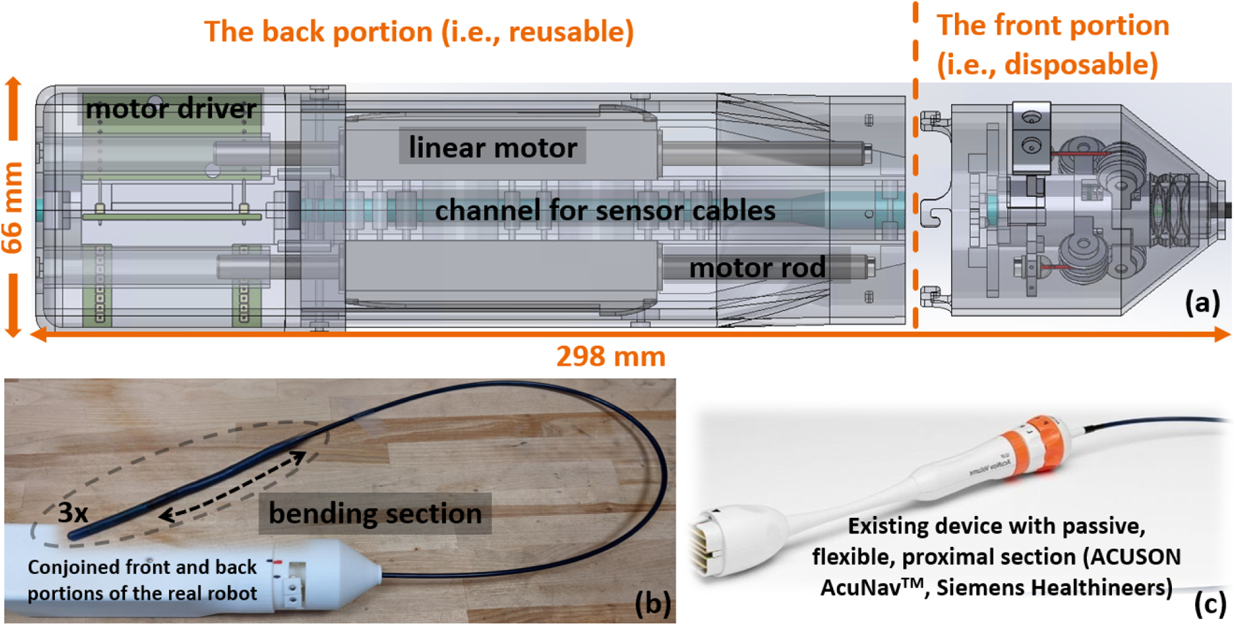
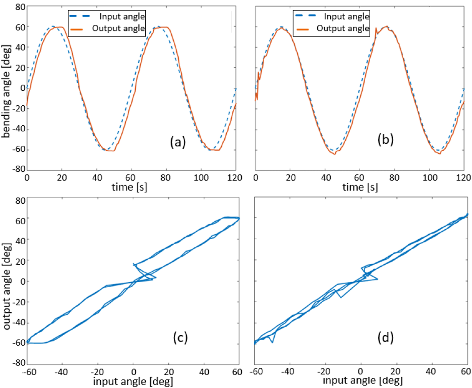
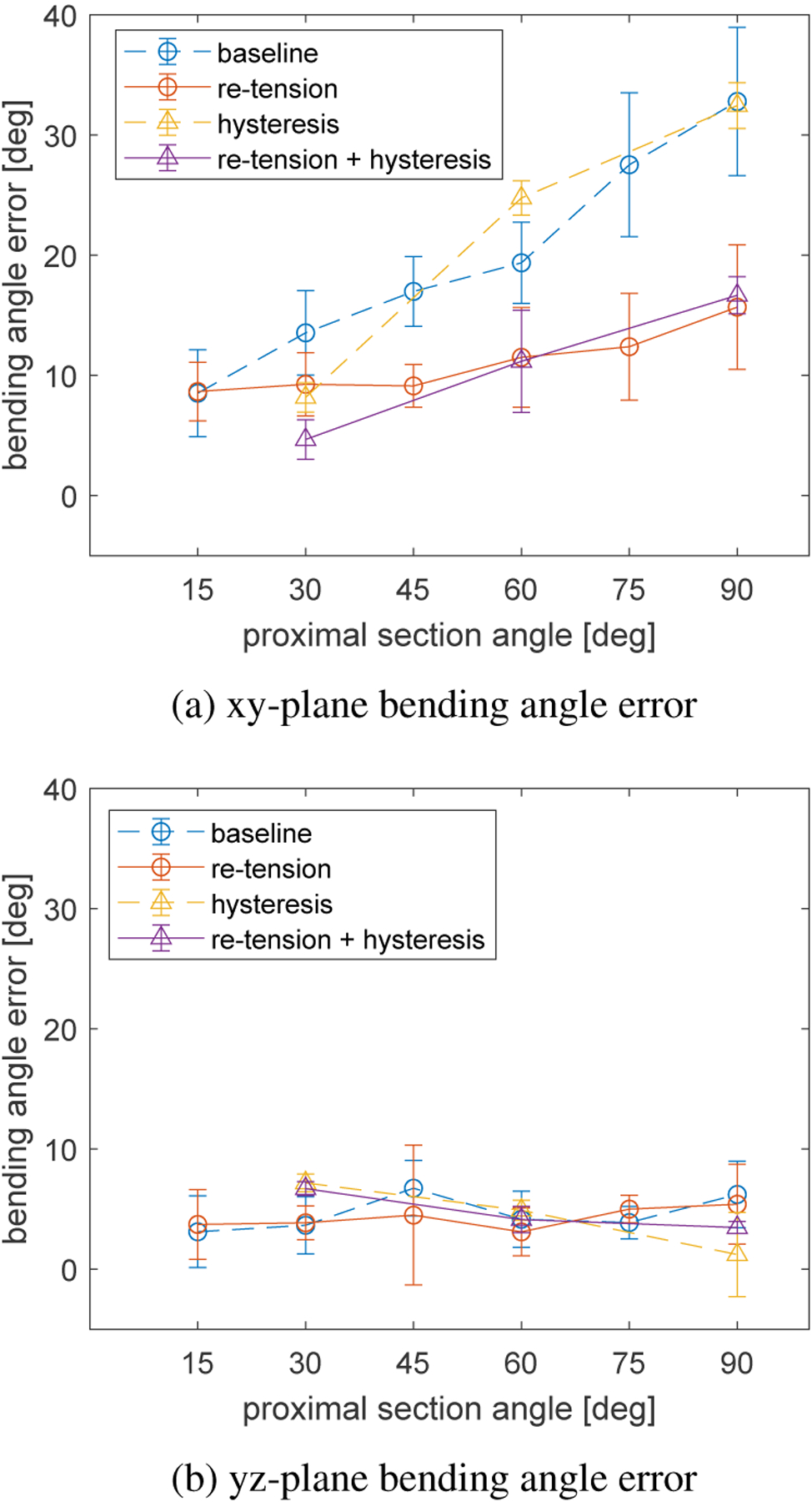
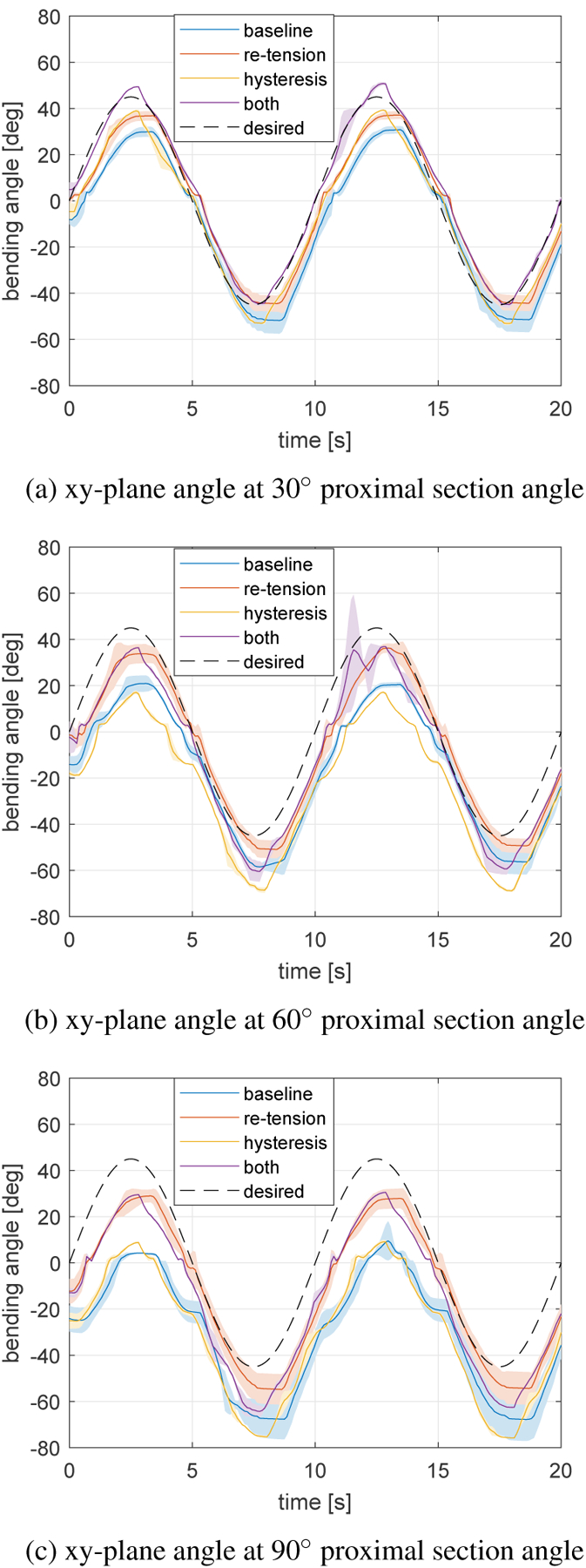
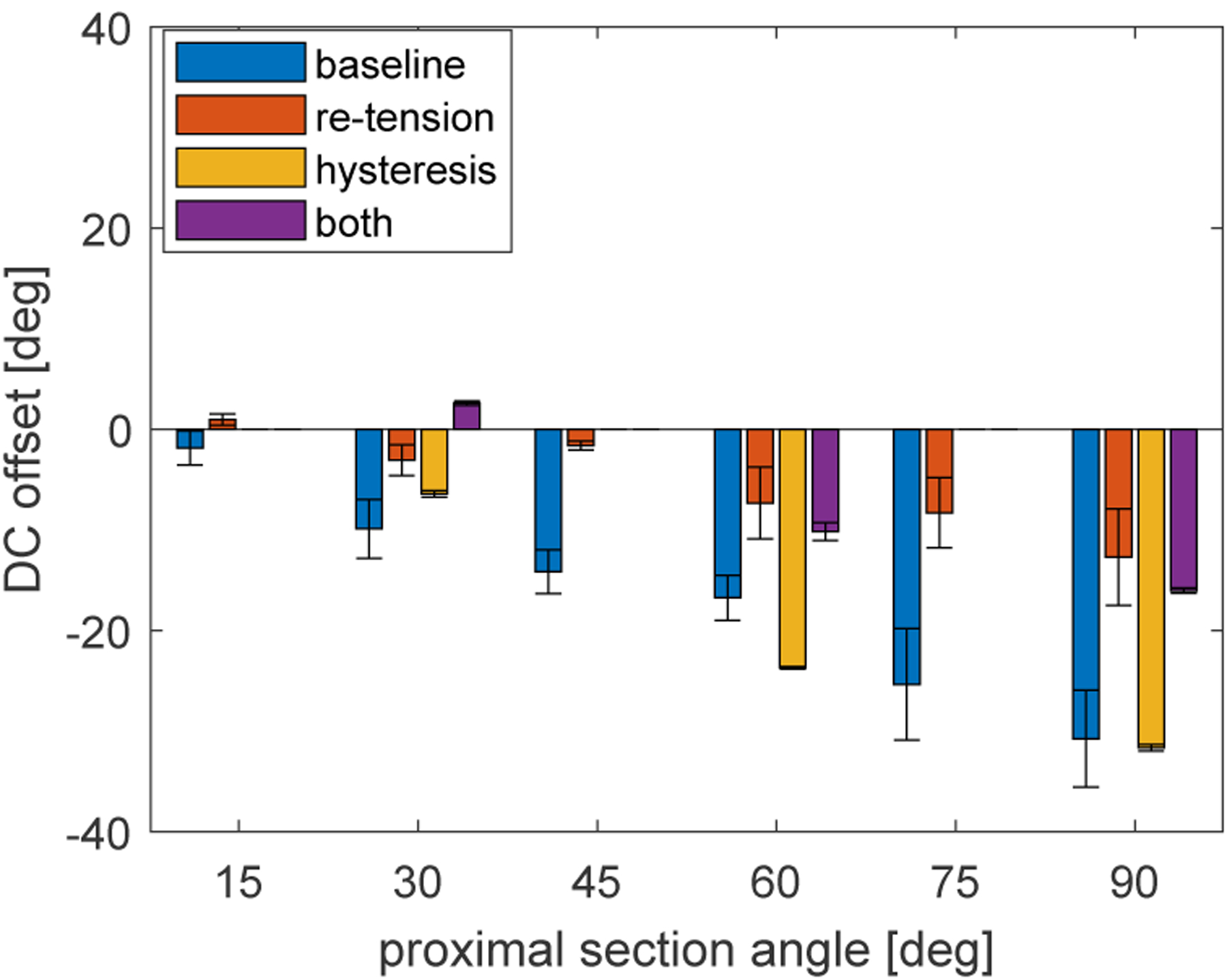
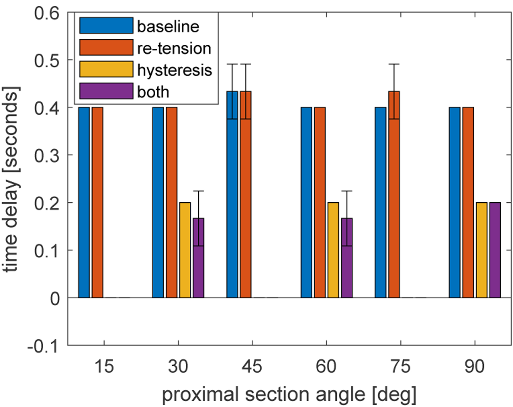
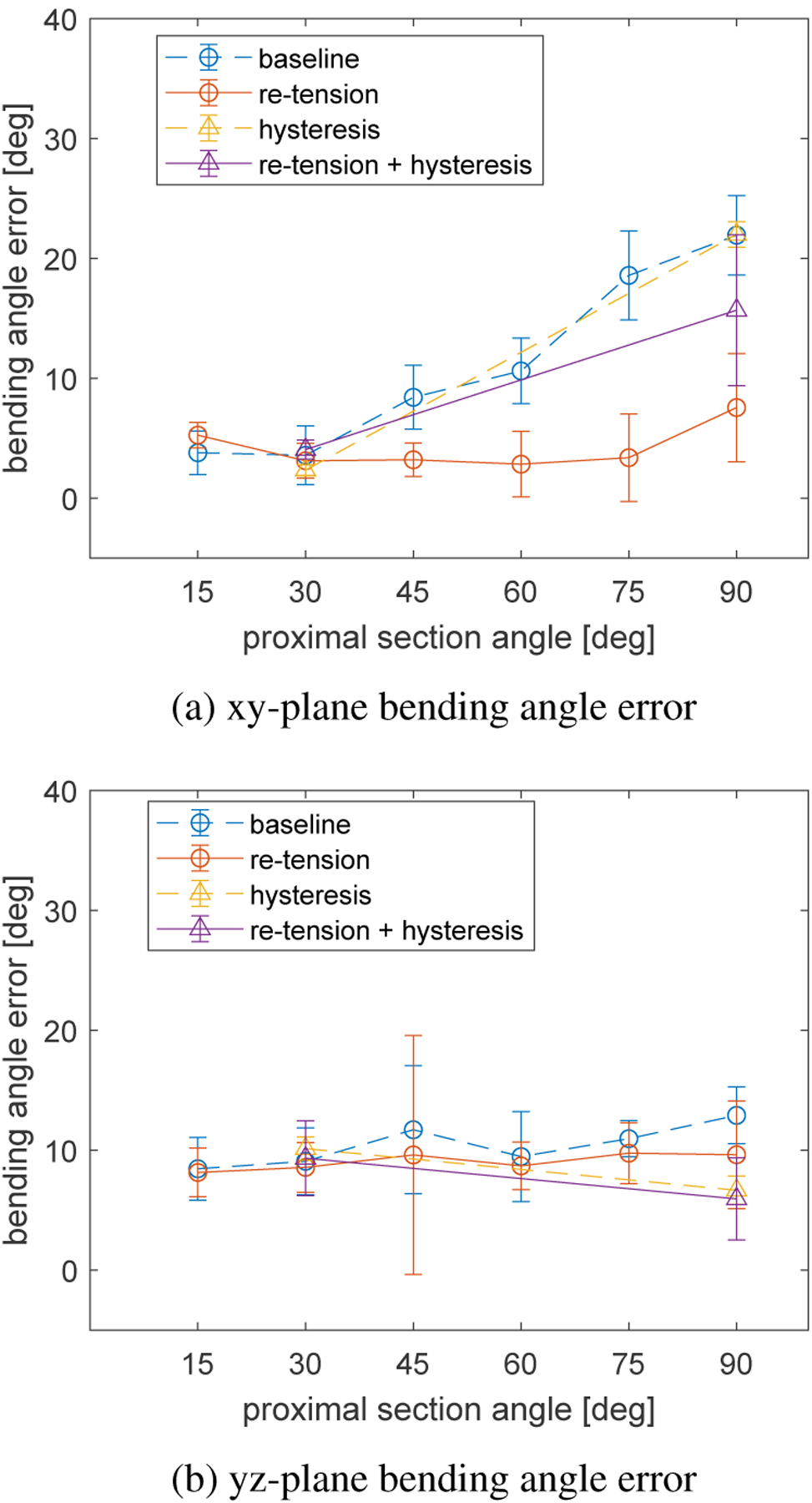
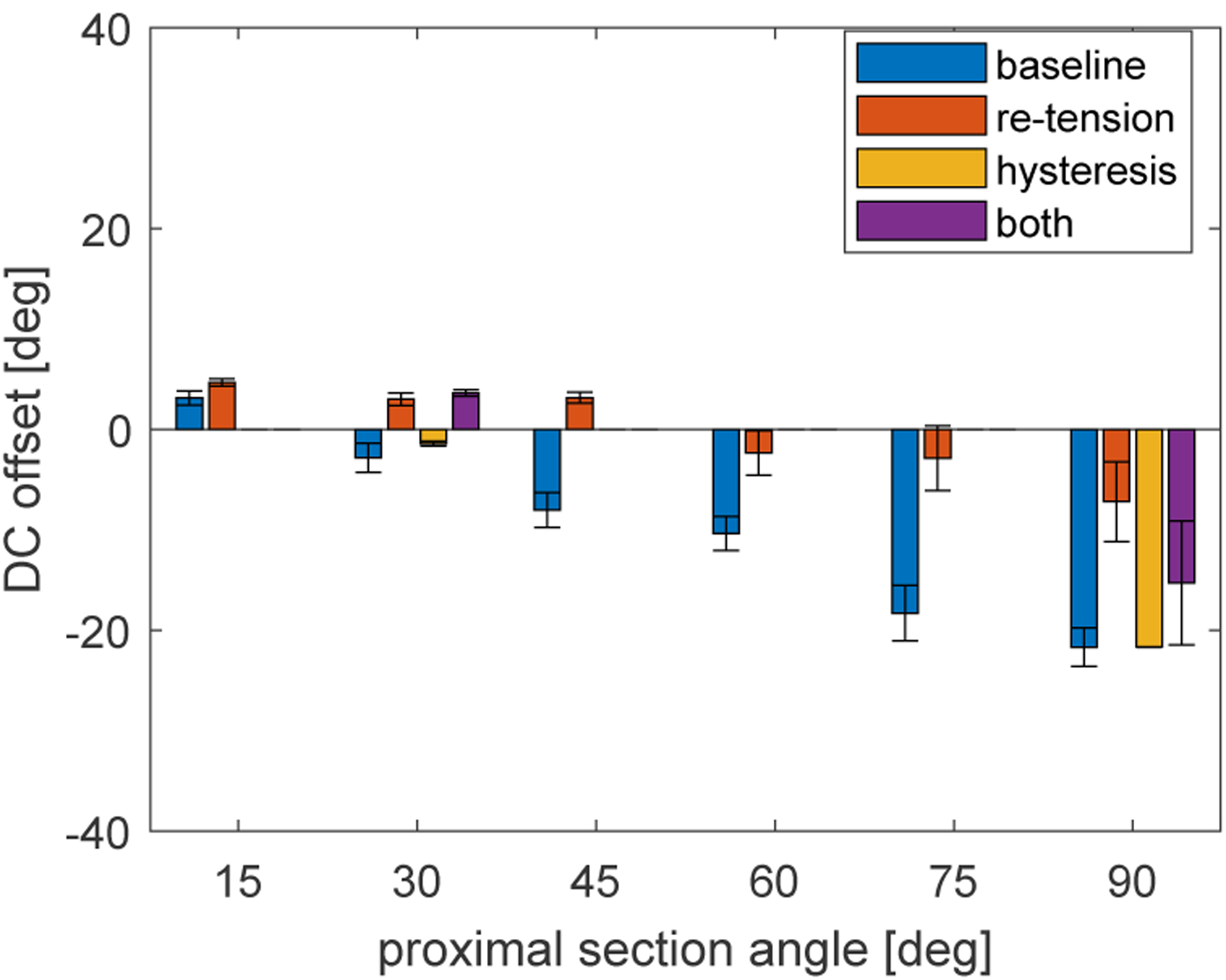
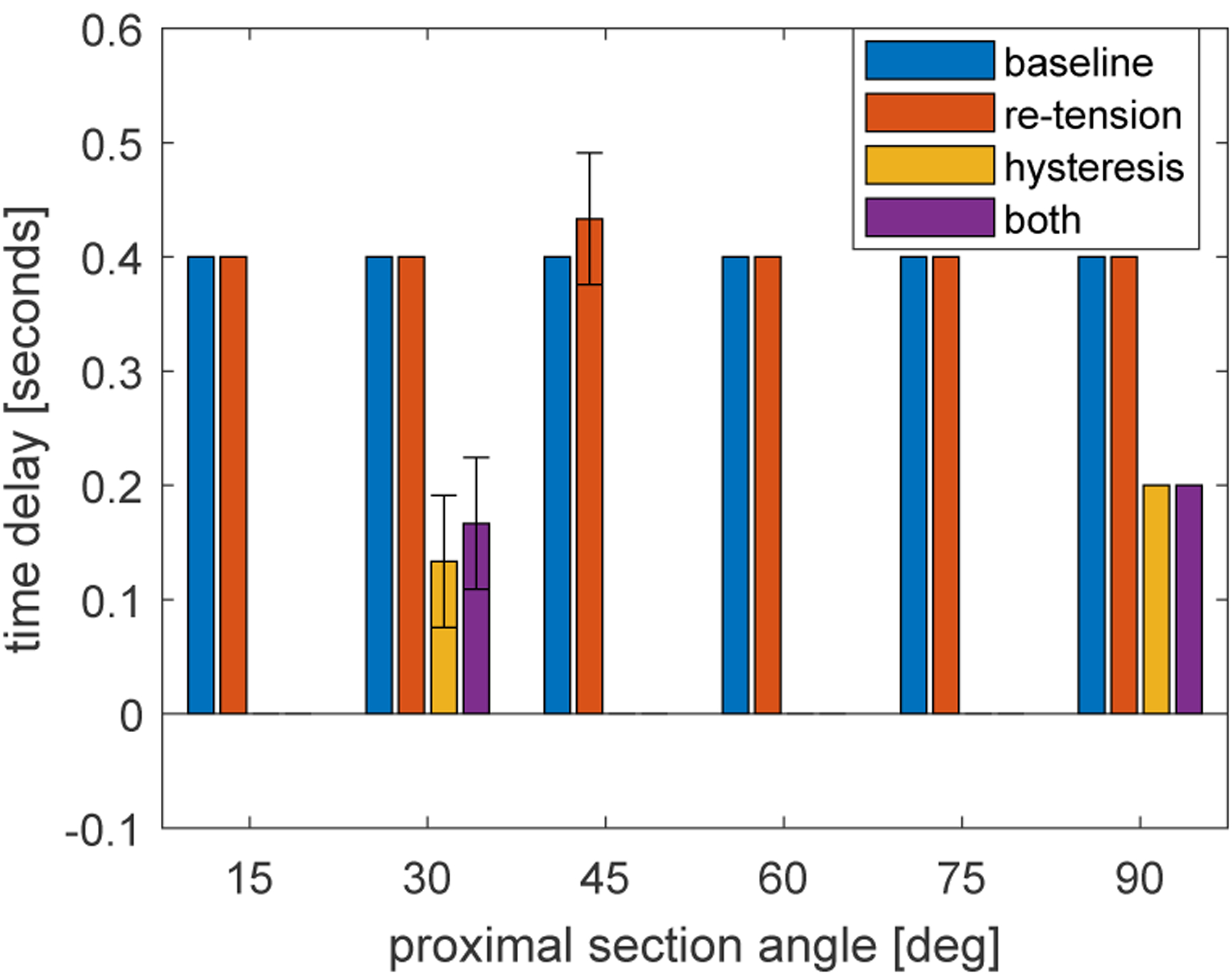
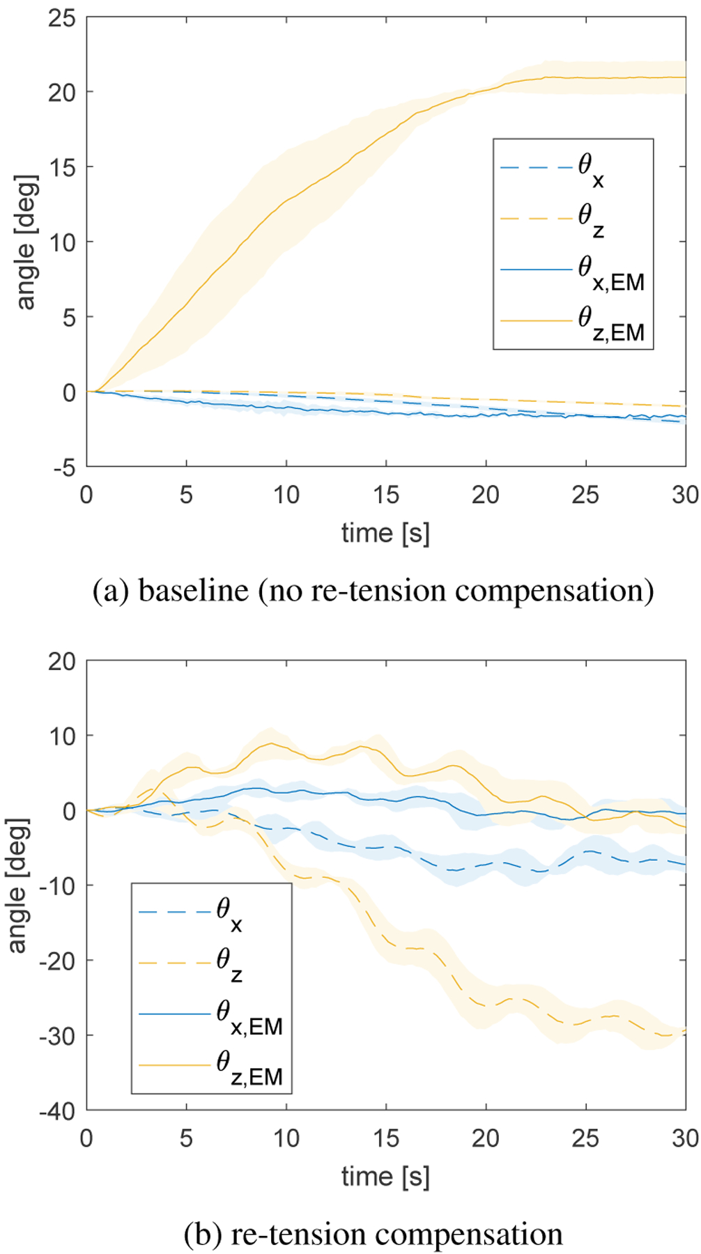
This work tackles practical issues which arise when using a tendon-driven robotic manipulator (TDRM) with a long, flexible, passive proximal section in medical applications. Tendon-driven devices are preferred in medicine for their improved outcomes via minimally invasive procedures, but TDRMs come with unique challenges such as sterilization and reuse, simultaneous control of tendons, hysteresis in the tendon-sheath mechanism, and unmodeled effects of the proximal section shape. A separable TDRM which overcomes difficulties in actuation and sterilization is introduced, in which the body containing the electronics is reusable and the remainder is disposable. An open-loop redundant controller which resolves the redundancy in the kinematics is developed. Simple linear hysteresis compensation and re-tension compensation based on the physical properties of the device are proposed. The controller and compensation methods are evaluated on a testbed for a straight proximal section, a curved proximal section at various static angles, and a proximal section which dynamically changes angles; and overall, distal tip error was reduced.


Figures

Fig. 1:
Fig. 1:
An overview of the catheter robot.
Fig. 2:
Fig. 2:
Disposable portion of the robot.
Fig. 3:
Fig. 3:
Reusable portion of the robot.
Fig. 4:
Fig. 4:
Conceptual side-view and cross-section. θz,κz, and rz are the bending angle, curvature, and radius of curvature about the z-axis (in the xy-plane). dxi,dzi are the coordinates of tendon i relative to the central axis (y-axis) of the robot.
Fig. 5:
Fig. 5:
Planar spring model for two tendons: L0,Ka, and Kb are the length, axial stiffness, and bending stiffness of the articulation section; lt,i,kt,i,di, and yi are the undeformed length, stiffness, distance from the central axis, and displacement of tendon i.
Fig. 6:
Fig. 6:
Phenomena in need of compensation.
Fig. 7:
Fig. 7:
Hysteresis curve with width w.
Fig. 8:
Fig. 8:
Experimental setup: testbed of robot has outer cover removed; device is clipped a few centimeters proximal to the articulation section; and black tape marks proximal section angles.
Fig. 9:
Fig. 9:
One result for yz-plane bending: (a) Time vs output angle without compensation (b) Time vs output angle with hysteresis compensation (c)(d) The input angle vs the output angle without/with hysteresis compensation.
Fig. 10:
Fig. 10:
Bending angle error for different compensation types and proximal section angles (xy-plane input).
Fig. 11:
Fig. 11:
Bending angle for different compensation types at three proximal section angles (xy-plane input).
Fig. 12:
Fig. 12:
Bending angle offset for different compensation types and proximal section angles (xy-plane input).
Fig. 13:
Fig. 13:
Bending angle time delay for different compensation types and proximal section angles (xy-plane input).
Fig. 14:
Fig. 14:
Bending angle error for different compensation types and proximal section angles (yz-plane input).
Fig. 15:
Fig. 15:
Bending angle offset for different compensation types and proximal section angles (yz-plane input).
Fig. 16:
Fig. 16:
Bending angle time delay for different compensation types and proximal section angles (yz-plane input).
Fig. 17:
Fig. 17:
Dynamic tests with re-tension compensation: dashed lines are angles according to the kinematics, and solid lines are measured by the EM sensor.

Similar articles

References

    1. Stereotaxis, 2020, Stereotaxis v-drive robotic navigation system, Feb. http://www.stereotaxis.com/products/vdrive.
    1. Kim Y-H, Collins J, Li Z, Chinnadurai P, Kapoor A, Lin CH, and Mansi T, 2022, “Automated catheter tip repositioning for intra-cardiac echocardiography,” International Journal of Computer Assisted Radiology and Surgery, 17, p. 1409–1417. - PubMed
    1. Reddy MD,VY, Neuzil MD,P, Malchano BS,ZJ, Vijaykumar BS,R, Cury MD,R, Abbara MD,S, Weichet MD,J, McPherson BS,CD, and Ruskin MD,JN, 2007, “View-Synchronized Robotic Image-Guided Therapy for Atrial Fibrillation Ablation,” Circulation, 115(21), May, pp. 2705–2714. - PubMed
    1. Agrawal A, Hogarth DK, and Murgu S, 2020, “Robotic bronchoscopy for pulmonary lesions: a review of existing technologies and clinical data,” Journal of Thoracic Disease, 12(6), June, pp. 3279–3286. - PMC - PubMed
    1. Intuitive Surgical, 2022, Ion platform - robotic-assisted bronchoscopy https://www.intuitive.com/en-us/products-and-services/ion.

LinkOut - more resources