Review
. 2024 Jan 23;14(3):239.
doi: 10.3390/nano14030239.

The Recent Progresses of Electrodes and Electrolysers for Seawater Electrolysis

Affiliations
Review

The Recent Progresses of Electrodes and Electrolysers for Seawater Electrolysis

Fan Zhang et al. Nanomaterials (Basel). .

Abstract

The utilization of renewable energy for hydrogen production presents a promising pathway towards achieving carbon neutrality in energy consumption. Water electrolysis, utilizing pure water, has proven to be a robust technology for clean hydrogen production. Recently, seawater electrolysis has emerged as an attractive alternative due to the limitations of deep-sea regions imposed by the transmission capacity of long-distance undersea cables. However, seawater electrolysis faces several challenges, including the slow kinetics of the oxygen evolution reaction (OER), the competing chlorine evolution reaction (CER) processes, electrode degradation caused by chloride ions, and the formation of precipitates on the cathode. The electrode and catalyst materials are corroded by the Cl- under long-term operations. Numerous efforts have been made to address these issues arising from impurities in the seawater. This review focuses on recent progress in developing high-performance electrodes and electrolyser designs for efficient seawater electrolysis. Its aim is to provide a systematic and insightful introduction and discussion on seawater electrolysers and electrodes with the hope of promoting the utilization of offshore renewable energy sources through seawater electrolysis.

Keywords: chlorine evolution reaction; electrode; electrolyser; oxygen evolution reaction; seawater electrolysis.


Conflict of interest statement

Author Fan Zhang, Xiaofeng Chen and Shengxiao Zhao were employed by the company Power China Huadong Engineering Corporation Limited. The remaining authors declare that the research was conducted in the absence of any commercial or financial relationships that could be construed as a potential conflict of interest.

Figures
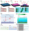
Figure 5
Figure 5
(ac) The MnOx on top of the IrOx layer, blocking ClOR by preventing Cl from reaching the IrOx underneath [77]. Copyright 2018, American Chemical Society. Scheme of Cl crossing through the NiFe−LDH with the PO43− anion (d) and without any anions intercalation (e) [79], Copyright 2023, Wiley. (f) Catalysts optimization (left) and electrolyte optimization (right) to protect the metal substrate from Cl corrosion by adsorbing SO42− layer [81]. Copyright 2021, Wiley. (g) Lewis acid on the anode facilitates OER and inhibits chlorine chemistry [62]. Copyright 2023, Nature. (h) The Schematic illustration of in situ AgCl effectively repel free Cl through strong common-ion repulsive effect [16]. Copyright 2023, Wiley. (i) The schematic illustration for structure evolution and OER mechanism transfer in alkaline pure water and alkaline seawater [82]. Copyright 2023, Wiley. (j) The schematic diagram of the two pitting initiation mechanisms [83]. Copyright 2023, Nature.
Figure 1
Figure 1
Mechanism of HER in acidic (a) and alkaline (b) solutions [32]. Copyright 2020, American Chemical Society. (c) Volcano plot for the HER for various pure metals and metal overlayers. (d) Computational high−throughput screening for |GH| on 256 pure metals and surface alloys [33]. Copyright 2006, Nature.
Figure 2
Figure 2
Mechanism of OER consists of (a) adsorbate evolution mechanism (AEM), (b) lattice oxygen mechanism (LOM) [34]. Copyright 2023, American Chemical Society. (c) Pourbaix diagram for artificial seawater model. (d) Maximum allowed overpotential of OER to ensure 100% selective in seawater splitting [35]. Copyright 2016, Wiley.
Figure 3
Figure 3
(a) Diagram of Pt−Ni@NiMoN electrocatalyst for seawater HER [37]. Copyright 2023, Royal Society of Chemistry. (b) Diagram of Ru−Cu nano-heterostructures for efficient HER [15]. Copyright 2023, American Chemical Society. (c) Proposed structure of the Ni−SN@C catalyst [49]. Copyright 2021, Wiley. (d) Scheme of hetero-structured CeO2/α−MoC/β−Mo2C electrocatalyst [44]. Copyright 2022, Elsevier. (e) Scheme of Lewis acid to facilitate HER and prevent precipitate formation [62]. Copyright 2023, Nature. (f) Scheme of Ni(OH)2 membrane grown in situ to repel Cl [63]. Copyright 2023, Royal Society of Chemistry.
Figure 4
Figure 4
Waterfallplot of normalized and background-subtracted (003) peak obtained during in situ WAXS in 0.1 M KOH and potential steps for (a) NiFe LDH and (b) CoFe LDH [71]. Copyright 2022, Tsinghua University Press. (c) in situ Raman spectra collected for BZ-NiFe-LDH/CC at different potential [72]. Copyright 2020, Nature.
Figure 6
Figure 6
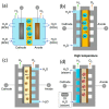
Configuration for seawater electrolysis: (a) alkaline water electrolysis (AWE) electrolyser; (b) anion exchange membrane water electrolysis (AEMWE) electrolyser; (c) proton exchange membrane water electrolysis (PEMWE) electrolyser; (d) solid oxide electrolysis cell (SEOC) [85]. Copyright 2023, Nature.
Figure 7
Figure 7
(a) Overall water/seawater splitting performance of Ni2P-Fe2P/NF and the Pt/C||IrO2 pair in 1 M KOH and 1 M KOH seawater. (b) Comparison of the voltages at a current density of 100 mA cm−2 for seawater splitting between Ni2P-Fe2P/NF and other electrocatalysts [87]. Copyright 2020, Wiley. (c) LSV curves of the NiFe@DG||Pt/C and RuO2||Pt/C electrolysers. (d) Comparison of voltages at 10 and 100 mA cm−2 for the NiFe@DG||Pt/C pair with recently reported catalysts. (e) Durability measurement of the AWE electrolyser at 10 mA cm−2. (f) Photograph of seawater electrolysis driven by a commercial Si solar cell [88]. Copyright 2023, American Chemical Society.
Figure 8
Figure 8
(a) Schematic of a forward-osmosis water-splitting cell [28]. Copyright 2022, American Chemical Society. (b) Schematic diagram of a typical seawater electrolysis system. (c) The liquid–gas–liquid phase transition-based migration mechanism of the water purification and migration process and the driving force [27]. Copyright 2022, American Chemical Society.
Figure 9
Figure 9
(a) Scheme for the asymmetric electrolyser with Na+ exchange membrane. (b) The pourbaix diagram of water [19]. Copyright 2023, Nature. (c) Water electrolyser using a vapor feed at the anode and saltwater at the cathode and (d) water electrolyser using saltwater at the anode and the cathode [20]. Copyright 2021, Royal Society of Chemistry.
Figure 10
Figure 10
(a) AEMWE electrolyser configured with asymmetric feeds [97]. Copyright 2020, Royal Society of Chemistry. (b) schematic of AEMWE configuration on alkaline seawater electrolysis [98]. Copyright 2023, American Chemical Society. Schematic representing (c) the cell configuration (d) the cell electrode assembly [22]. Copyright 2023, Elsevier. (e) schematic illustration of hydrogen production by AEMWE electrolyser in practical alkaline seawater [21]. Copyright 2021, Royal Society of Chemistry.
Figure 11
Figure 11
(a) Scheme of water transport in BPM electrolysers [99]. Copyright 2020, American Chemical Society. (b) Scheme of the hydroxide precipitation alleviated by the BPM designs [100]. Copyright 2022, Wiley. Cross−sectional schematic of a zero−gap (c) BPMWE and (d) PEMWE [101]. Copyright 2023, Cell. (e) BPM and AEMWE electrolyser reference polarization curves [99]. Copyright 2020, American Chemical Society. (f) Structure and performance of a BPMWE MEA with the different thickness AEM impregnation layer at the anode [102]. Copyright 2020, American Chemical Society.
Figure 12
Figure 12
(a) Schematic of flat-tube solid oxide electrolysis cell; (b) Cross-sectional structure of the electrolysis cell; (c) schematic of the electrolysis test system [25]. Copyright 2023, Elsevier. (d) Long-term electrolysis voltages of cells with different temperatures and seawater steam content [24]. Copyright 2023, Royal Society of Chemistry. (e) Durability test for the contaminated cell at 0.8 A cm−2 and 800 °C [103]. Copyright 2017, Elsevier.

Similar articles

References

    1. Wang F., Harindintwali J.D., Yuan Z., Wang M., Wang F., Li S., Yin Z., Huang L., Fu Y., Li L., et al. Technologies and perspectives for achieving carbon neutrality. Innovation. 2021;2:100180. doi: 10.1016/j.xinn.2021.100180. - DOI - PMC - PubMed
    1. Msheik M., Rodat S., Abanades S. Methane Cracking for Hydrogen Production: A Review of Catalytic and Molten Media Pyrolysis. Energies. 2021;14:3107. doi: 10.3390/en14113107. - DOI
    1. Wang C., Wang Y., Chen M., Liang D., Yang Z., Cheng W., Tang Z., Wang J., Zhang H. Recent advances during CH4 dry reforming for syngas production: A mini review. Int. J. Hydrogen Energy. 2021;46:5852–5874. doi: 10.1016/j.ijhydene.2020.10.240. - DOI
    1. Dehane A., Nemdili L., Merouani S., Ashokkumar M. Critical Analysis of Hydrogen Production by Aqueous Methanol Sonolysis. Top. Curr. Chem. 2023;381:9. doi: 10.1007/s41061-022-00418-1. - DOI - PubMed
    1. Ulejczyk B., Nogal Ł., Młotek M., Krawczyk K. Enhanced production of hydrogen from methanol using spark discharge generated in a small portable reactor. Energy Rep. 2022;8:183–191. doi: 10.1016/j.egyr.2021.11.290. - DOI

LinkOut - more resources